C−LRV lift control valve Product description
31/92
300−I−9010212−E−10/08.08
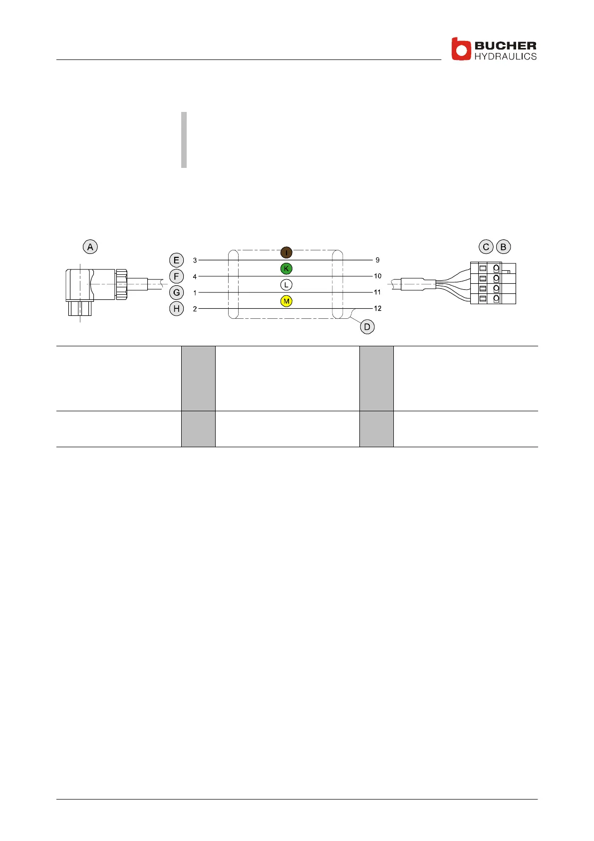
1.6 IWK−1 feedback cable
Important: The feedback cable must be run from the lift control valve
directly to the NTA−2 power supply unit without any intermediate ter-
minals. Any discontinuity in the feedback cable (break, kink, etc.) can
endanger trouble−free operation.
It is essential that connection 2 is ground−bonded to terminal 12, other-
wise the null point of the sensor will not be stable.
If you cut the cable to length and terminate it yourself, be sure to wire it
correctly in accordance with the following diagram:
Legend A
B
C
D
Line socket with PG7 gland
NTA−2 connector
WAGO plug
Screen
E
F
G
H
Supply +15V
Signal 0...±13.4V
Supply −15V
Ground
Colours I
K
Brown
Green
L
M
White
Yellow