C−LRV lift control valve Installation and commissioning
50/92
300−I−9010212−E−10/08.08
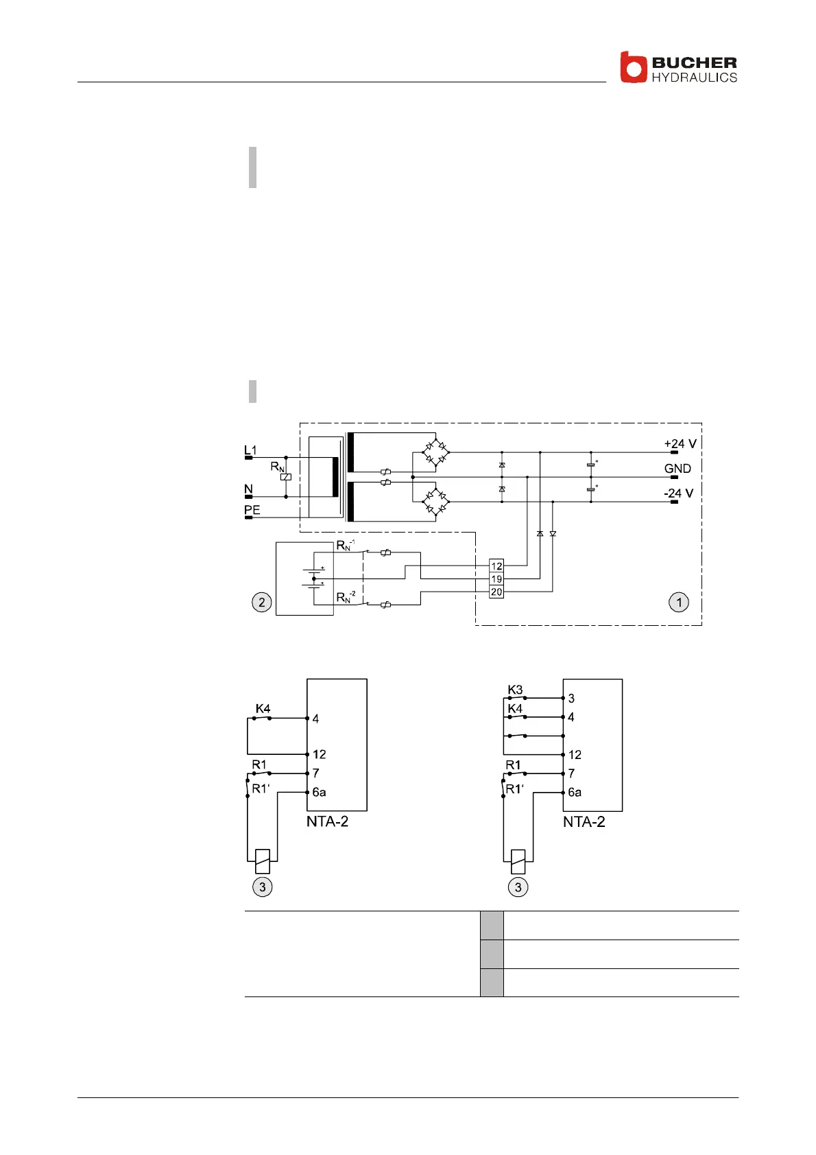
4.2.4 Electrical emergency−lowering 2 x 24 VDC
Important: the operator must undertake any further measures required
to ensure short−circuit and overvoltage protection.
If a mains (line) failure occurs, the power supply unit can be powered by
an external battery supply (2 x 24 V) through terminals 12, 19 and 20.
S Relay R
N
drops out when there is a power failure and the two nor-
mally−closed contacts R
N
−1
and R
N
−2
connect to the battery
I Inputs 19 and 20 have diode−protection from polarity reversal or feed-
back to the battery
S The lift can be lowered to a predefined stopping position by means of
"Slow DOWN" or auxiliary speed K6...K8 (travel signals are gener-
ated by the lift control system).
Important: only possible with 2 x 24V (or 4 x 12V) batteries
Slow DOWN Auxiliary speed
K6/K7/K8
21/22/23
Legend 1 NTA−2 power supply unit
2 Supplied by customer
3 DOWN solenoid