C−LRV lift control valve Installation and commissioning
59/92
300−I−9010212−E−10/08.08
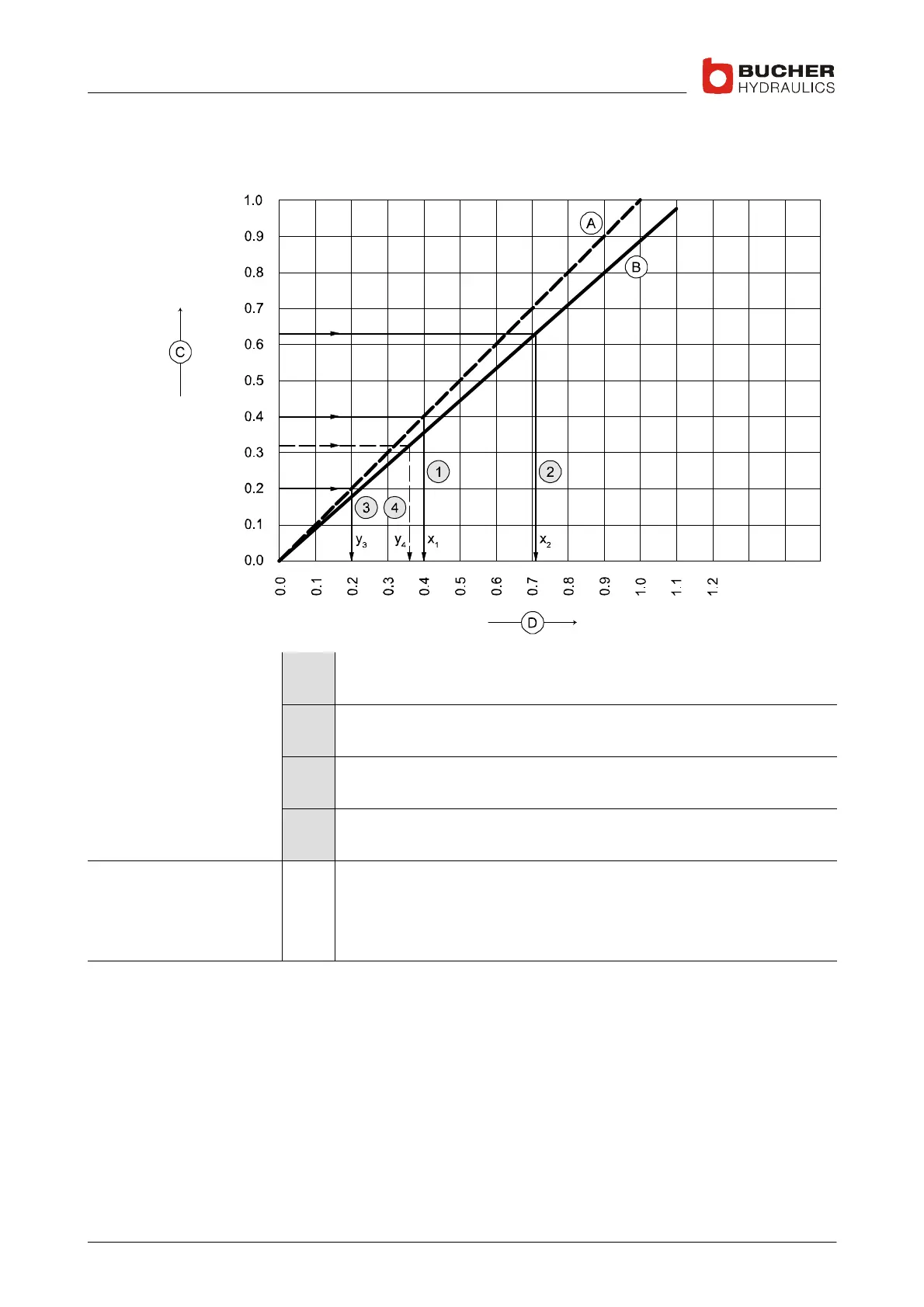
4.3.9 Required deceleration distance
Guidelines for positioning the deceleration switches.
Examples 1 Deceleration distance "X" for direct (1:1) drive
e.g.: v=0.4m/s → x
1
=0.4m
2 Deceleration distance "X" for indirect (2:1) drive
e.g.: v=0.63m/s → x
2
=0.71m
3 Deceleration distance "Y" for direct (1:1) drive (auxiliary speed)
e.g.: v=0.4m/s : 2 = 0.2m/s → y
3
=0.2m
4 Deceleration distance "Y" for indirect (2:1) drive (auxiliary speed)
e.g.: v=0.63 m/s : 2 → y
4
=0.32 m
Legend A
B
C
D
Direct drive (1:1)
Indirect drive (2:1)
Car speed [m/s]
Distance of deceleration switches before landing [m]
 Loading...
