C−LRV lift control valve Product description
24/92
300−I−9010212−E−10/08.08
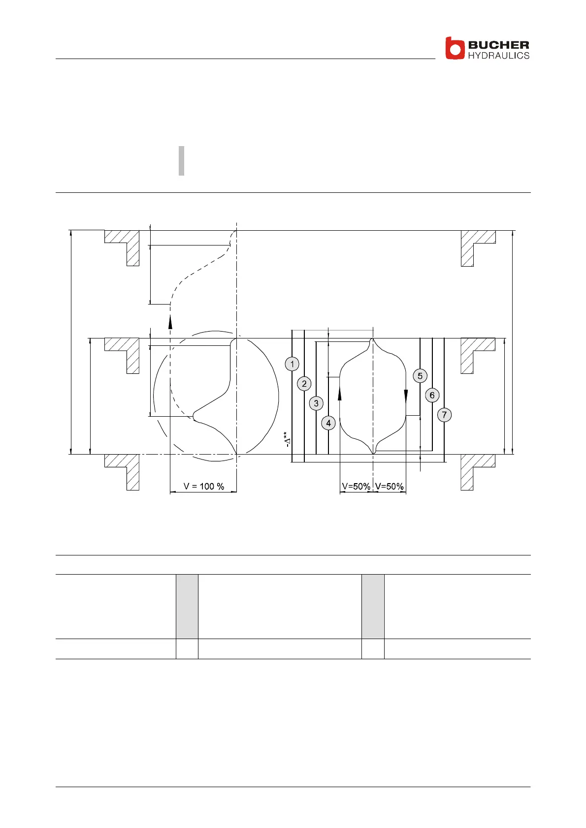
1.4.5 Travel and switching diagram for short travel distances
The electronics of the C−LRV valve make it possible to control stops at
mezzanines and similar short travel distances with the same ride comfort
as in normal travel.
Important: The maximum speed should be reduced to a value that,
despite the short travel distance, can actually be attained.
Short distance between floors with normal speed
(slow−speed travel distance too long)
Short distance between floors with reduced speed
(K6)
N
K
N
K
ZX
ZY
ZY
XZ
Y **
**
*
**
***
V
Motor run−on time of 0.5 ... 1s
Drop−out delay of 0.5 ... 1s, after drop out of K4 + K6
K2 and K2 not until Δ connection
Adjust the speed to suit the circumstances (e.g. 50%)
X
Y
Z
Deceleration switch at normal speed
Deceleration switch at reduced speed
Soft−Stop is not separately adjustable
Legend 1
2
3
4
Motor contactor ON
Safety relay R2 closed
K2 + K6 closed
K1 closed
5
6
7
K3 closed
K4 + K6 closed
Safety relay R1 closed
N Normal distance between floors K Short distance between floors
 Loading...
