C−LRV lift control valve Installation and commissioning
49/92
300−I−9010212−E−10/08.08
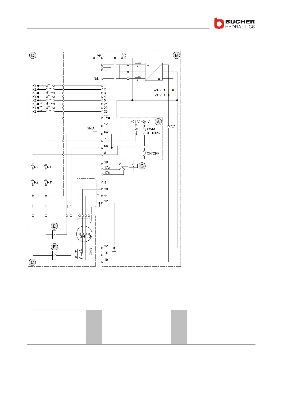
4.2.3 Wiring the power supply unit
300−1−10009300
1
2
3
4
5
21
22
23
6a/6b
7
8
9
10
11
12
20
19
Legend
Fast UP
Slow UP
Fast DOWN
Slow DOWN
Inspection speed
Speed reduction
Speed reduction
Speed reduction
Common
DOWN solenoid
UP solenoid
Stabilised voltage supply
+15V
Feedback signal
(input)
Stabilised voltage supply
−15V
GND, test/measurement
−24 V emergency power
supply
+24 V emergency power
supply
* When contact K5 closes, the C−DELCON’s two "fast"
speeds drop to a preset percentage of their nominal
values. The setting is adjustable between 20−80%
** When contacts K6, K7 or K8 close, the C−DELCON´s
two "fast" speeds drop to a preset percentage of their n
ominal values. The settings are adjustable between
20−100%
K1−K8, potential−free contacts or semiconductors
R1+R2 as per EN81−2, 12.4.1/12.4.2
Legend A
B
C
D
C−DELCON
NTA−2
C−LRV
Control cabinet (customer’s)
E
F
G
DOWN solenoid
UP solenoid
SIU−1 demand/feedback moni-
toring
SIU−4 v ≤0.3m/s