C−LRV lift control valve Installation and commissioning
58/92
300−I−9010212−E−10/08.08
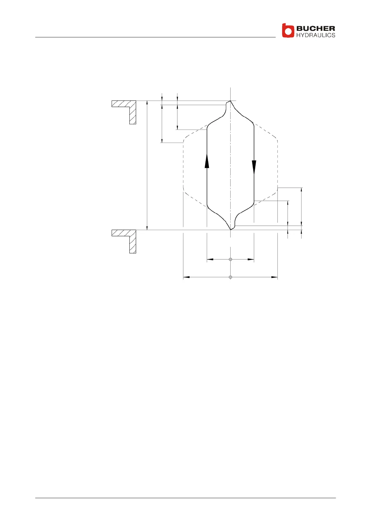
4.3.8 Positioning the shaft switches for the deceleration distance
The spacing of the shaft switches depends on the car speed
⇒ 4.3.9
v=50%
v=50%
v=100% v=100%
Aux. speed e.g.
Time t
X
ZY
Z
YZ
ZX
X Deceleration distance (shaft switches) for maximum speed
Y Deceleration distance (shaft switches) for auxiliary speed (for example, 50% of
maximum speed; adjustable in C−DELCON from 20–100%)
Z Stop−switch before landing (20–30mm) (soft−stop travel is controlled by the
C−DELCON)
 Loading...
