C−LRV lift control valve Product description
23/92
300−I−9010212−E−10/08.08
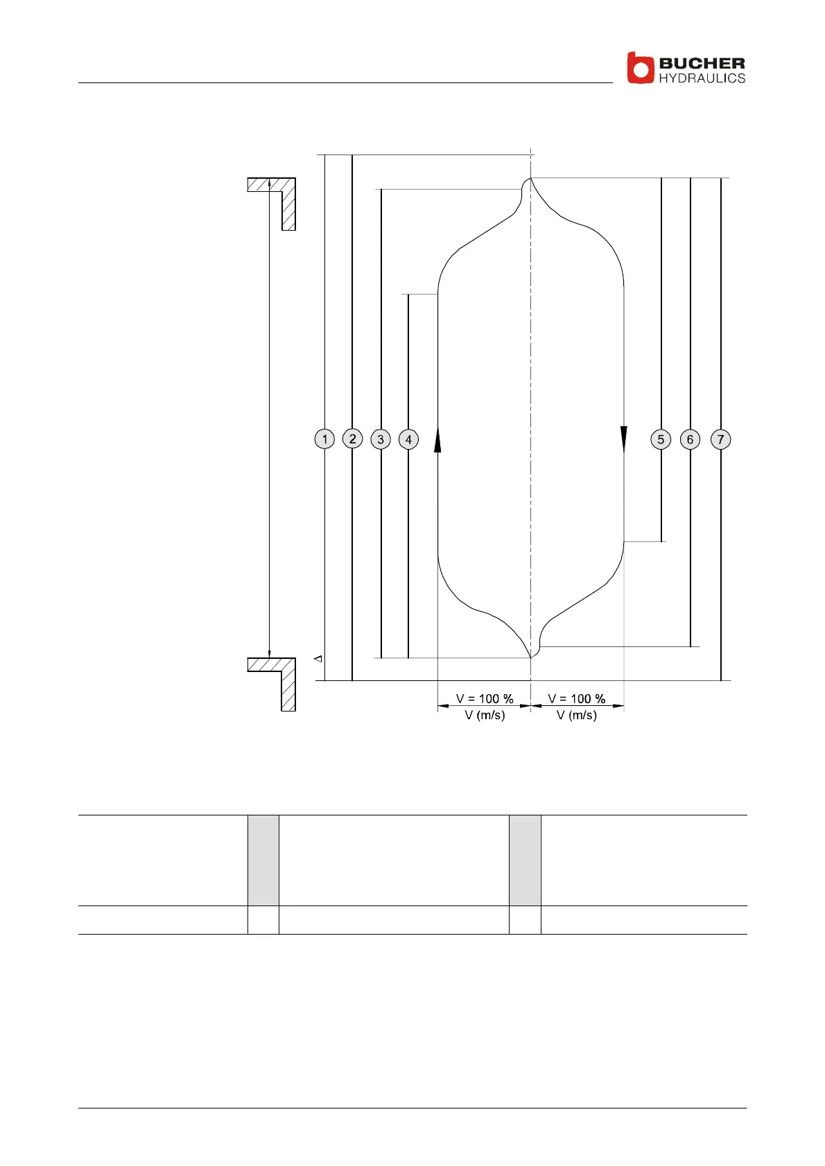
1.4.4 Travel and switching diagram for normal travel distance
**
*Y−
N
* motor run−on time of 0.5 ... 1s
** Drop−out delay of 0.5 ... 1s
Y−Δ Y starting time of up to approx.
3s with Y−Δ,
K1 and K2 not until Δ connection
Legend 1
2
3
4
Motor contactor ON
Safety relay R2 closed
K2 "Slow UP" closed
K1 "Fast UP" closed
5
6
7
K3 "Fast DOWN" closed
K4 "Slow DOWN" closed
Safety relay R1 closed
N Normal distance between floors
 Loading...
