18
Installation and maintenance instructions Logano G334 X gas-fired boiler • Issue 09/2005
We reserve the right to make any changes due to technical modifications.
Boiler installation7
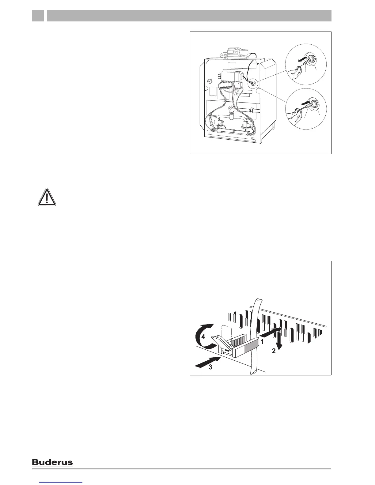
Installation of boiler water sensor
7. Route boiler water sensor wiring bundle under the
front boiler cover to the measuring point (immersion
well). Discard quadrant filler apart from sensor
bundle.
8. Remove quadrant (blanking piece) from the
immersion well.
9. Insert the Honeywell boiler water sensor and
Logamatic sensor bundle into the immersion well to
the stop to replace the quadrant.
10. Press sensor clip (included with control) from the
side or from above to the head of the immersion well.
11. Carefully roll up unnecessary wiring and capillaries
and stow in the Logamatic 2107 control.
Power connection and connections of additional
components
Connect to the power supply as specified by the local
code.
12. Route all wiring to the control through the wiring
opening and connect as specified by the control
circuit diagram.
Install strain relief
Secure all wiring with wiring clips (included with control):
– Insert wiring clip with wiring from above into the slot
of the clip frame; the lever bar must point upwards
(step 1).
– Slide wiring clip down (step 2).
– Press (step 3).
– Move lever up (step 4).
Fig. 13 Front of boiler
1 Measuring point (immersion well)
2 Quadrant (blanking piece)
3 Boiler water sensor (Logamatic 2107 control)
1
2
3
1
WARNING!
FIRE DANGER
Hot boiler components may damage
electrical wiring.
z Make sure that all wiring is routed in the
ducts or on outside the boiler insulation.
Fig. 14 Secure wiring with wiring clip
1
 Loading...