2003 Buell XB9S: Chassis 2-97
HOME
SIDESTAND DISASSEMBLY
1. Remove two fasteners from the left side of chin fairing.
NOTE
Sidestand assembly does not have to be removed from
motorcycle in order to remove sidestand leg.
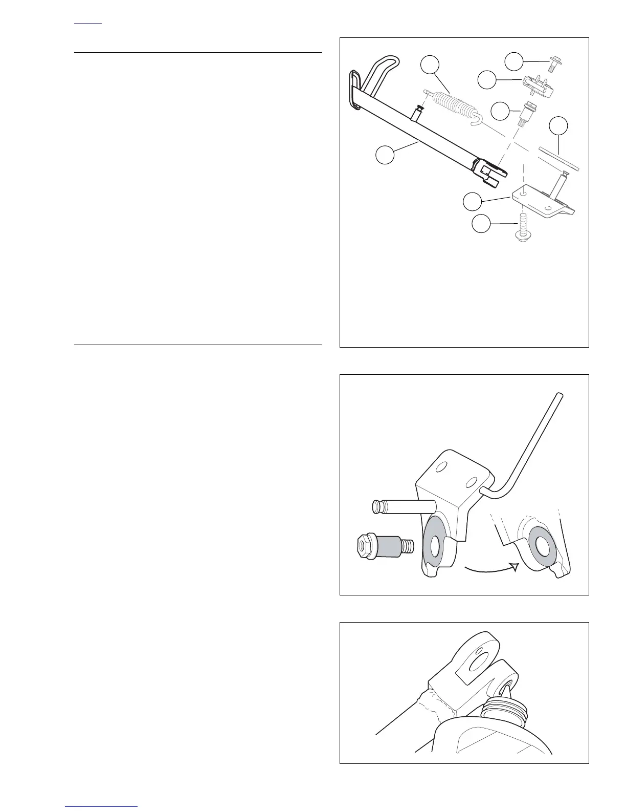
2. See Figure 2-118. Remove sidestand switch (6). See
2.43 SIDESTAND ASSEMBLY/ SIDESTAND SWITCH.
3. Remove sidestand leg (1).
a. Retract sidestand leg.
b. Remove sidestand spring (8) and spring extension
plate (4) using SNAP-ON SPRING TOOL (Part No.
HE-52B).
c. Remove sidestand pivot bolt (5).
d. Extend sidestand leg and remove.
SIDESTAND ASSEMBLY
1. Install sidestand leg (1).
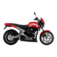
a. See Figure 2-118. Lubricate sidestand pivot bolt (5)
and mating portions on sidestand bracket (2) with
WHEEL BEARING GREASE (Part No. 99855-89) as
shown in Figure 2-119.
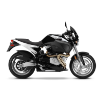
b. See Figure 2-120. Apply LOCTITE 272 (Red) to
threaded area (clevis) of sidestand leg.
NOTE
Applying LOCTITE to threaded area of clevis on sidestand
leg, instead of threads on the pivot bolt, will eliminate build-up
between clevis and sidestand bracket which can interfere with
the applied lubricant.
c. See Figure 2-118. Install sidestand (1) and side-
stand pivot bolt (5) tightening to 18-20 ft-lbs (24-
27 Nm).
d. Retract sidestand leg.
e. Install spring extension plate (4) and sidestand
spring (8) using SNAP-ON SPRING TOOL (Part No.
HE-52B).
NOTE
Extension plate should curve away from primary chain adjust-
ment screw to allow for clearance around adjustment screw.
2. See Figure 2-118. Install sidestand switch (6). See 2.43
SIDESTAND ASSEMBLY/ SIDESTAND SWITCH.
3. Install two fasteners into the left side of chin fairing and
tighten.
Figure 2-118. Sidestand Assembly
Figure 2-119. Lubricating Points (Shaded Areas)
Figure 2-120. Threaded Area for Loctite Application
1. Sidestand leg
2. Sidestand bracket
3. Bracket fastener
4. Spring extension plate
5. Sidestand pivot bolt
6. Sidestand switch
7. Switch fastener
8. Spring
b0946x2x
1
8
2
7
5
4
3
6








 To Next Page