2003 Buell XB9S: Electrical 7-17
HOME
TESTING/REPLACEMENT
Sidestand Switch
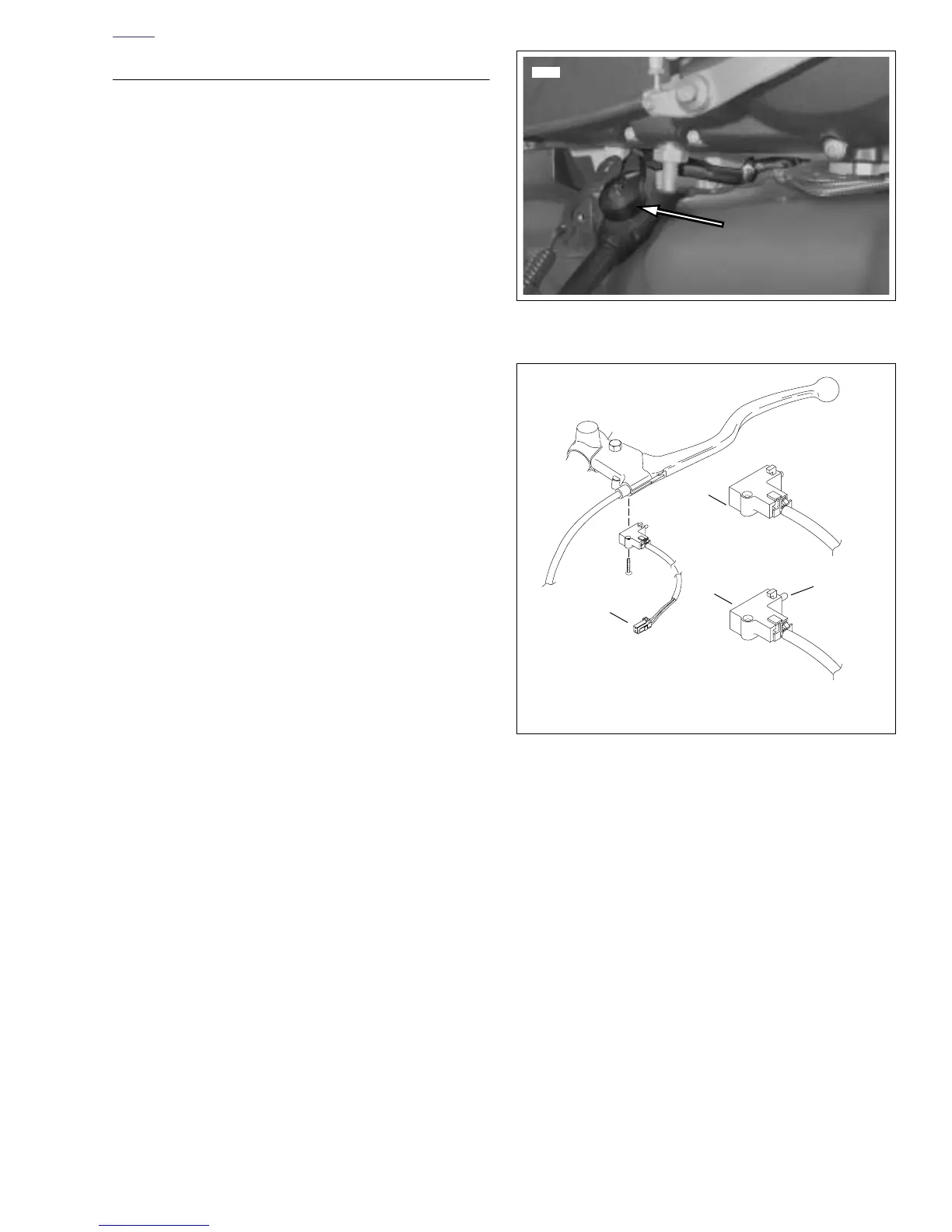
See Figure 7-14. The sidestand switch is a rotary type switch.
The switch completes a path to ground for the ignition relay
when the sidestand is in the retracted position. Test the switch
as follows:
1. Remove heat shrink tubing from sidestand switch con-
nector [60].
2. Unplug the 2-place sidestand switch connector [60].
3. Test the switch using an ohmmeter.
a. With sidestand down (switch open), the switch
should show ∞ ohms (infinite ohms).
b. With sidestand up (switch closed), the switch should
show 0 ohms or little resistance.
4. Replace the assembly with a new switch if necessary.
See 2.43 SIDESTAND ASSEMBLY.
5. Replace heat shrink tubing.
Clutch Switch
See Figure 7-15. The clutch switch attaches to the clutch con-
trol lever bracket. The switch completes a path to ground for
the ignition relay and the starter relay when the clutch is dis-
engaged. Test the switch as follows:
1. Unplug the 2-place clutch switch connector [95].
2. Test the switch using an ohmmeter.
a. With clutch engaged (1) (switch open), the switch
should show ∞ ohms (infinite ohms).
b. With clutch disengaged (2) (switch closed), the
switch should show 0 ohms or little resistance.
3. Replace the assembly with a new switch if necessary.
See 2.24 CLUTCH HAND LEVER.
Figure 7-14. Sidestand Switch
Figure 7-15. Clutch Switch
b0393x7x
1. Clutch engaged (switch open)
2. Clutch disengaged (switch closed)
3. Connector [95]
Trigger
Button
3
1
2















 To Next Page