EasyManua.ls Logo

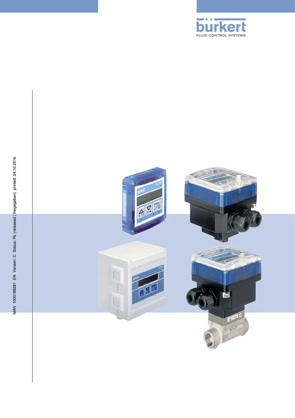
Burkert 8025 - User Manual

Burkert 8025
140 pages
Print Icon
To Next Page IconTo Next Page
Loading...
Operating Instructions
Bedienungsanleitung
Manuel d‘utilisation
Type 8025 - 8035 - SE35
BATCH
Batch controller
Dosiergerät
Contrôleur de dosage

Table of Contents

Other manuals for Burkert 8025

Questions and Answers

  • D
    danielreedSep 2, 2025
    What to do if my Bürkert Transmitter displays ERROR 6?
    • K
      Karen MelendezSep 3, 2025
      If your Bürkert Transmitter displays 'ERROR 6', it means a memory read error occurred, resulting in the loss of totalizer values. To fix this, press the ENTER key to acknowledge the error. This action will reset the totalizers.
  • K
    kennethwoodsSep 3, 2025
    Why does my Bürkert Transmitter show 'PU H LIM'?
    • H
      Heather RojasSep 3, 2025
      If the Bürkert Transmitter displays 'PU H LIM', it means that the pulse value times the K-factor of the device is greater than 1000000, indicating that the entered volume for a pulse is too high. To fix this, enter a lower volume per pulse and check the K-factor value.
  • J
    Jennifer DurhamSep 4, 2025
    Why does my Bürkert Transmitter show 'PU L LIM'?
    • T
      Taylor RoachSep 4, 2025
      If your Bürkert Transmitter displays 'PU L LIM', it indicates that the pulse value times the K-factor of the device is less than 1, meaning the entered volume for a pulse is too low. To resolve this, enter a higher volume per pulse and check the K-factor value.
  • T
    Thomas WilliamsSep 4, 2025
    How to troubleshoot a Burkert Controller when the device state LED is OFF?
    • R
      Robin FarrellSep 5, 2025
      If the device state LED on your Burkert Controller is off, it indicates that the device is not receiving power. You should first check the wiring to ensure it is correctly connected. Also, inspect the installation's fuse and replace it if needed. Verify that the installation hasn't been shut down and confirm that the power source is functioning correctly. If the issue persists after these checks, it may indicate a more complex problem.
  • L
    Lisa MillerSep 5, 2025
    Why is the device state LED on my Burkert Controller red with message 'PWRFAIL'?
    • M
      Matthew WagnerSep 5, 2025
      If the device state LED on your Burkert Controller displays red with the message 'PWRFAIL', it means the supply voltage is too low, preventing the device from functioning correctly. To resolve this, verify that the supply voltage is within the range of 12 to 36 V DC. If the problem continues after confirming the voltage, further assistance may be needed.
  • C
    charlessanchezSep 6, 2025
    What to do if Burkert Controller device state LED is red with message 'dosing being done...'
    • C
      Cameron WatsonSep 6, 2025
      If the device state LED on your Burkert Controller shows red with the message 'dosing being done...', it indicates that the rotational frequency of the paddle wheel exceeds 2.2 kHz. To fix this, check the flow rate in the pipe and adjust it as necessary. If the issue persists, further assistance might be required.
  • B
    Bobby StaffordSep 6, 2025
    Why is my Burkert Controller showing 'WARN. LOW'?
    • K
      karen94Sep 6, 2025
      If the device state LED on your Burkert Controller is orange and displays the message 'WARN. LOW', it signifies that the measured flow rate has remained below the minimum threshold for the set time delay during dosing. Check the flow rate in the pipe and its impact on the process. If needed, clean the flow sensor. After the dosing is complete, go to the Information menu and confirm the message.
  • D
    Dana WilliamsSep 7, 2025
    What does 'WARN. HIG' mean on my Burkert Controller?
    • M
      Matthew HicksSep 7, 2025
      If the device state LED on your Burkert Controller is orange and displays the message 'WARN. HIG', it means that the measured flow rate has remained above the maximum threshold for the set time delay during a dosing. You should check the flow rate in the pipe and its effect on the process. Clean the flow sensor, if necessary. After the dosing is finished, access the Information menu and confirm the message.

Summary

Operating Instructions

About Operating Instructions

Guidance on manual usage, symbols, and document validity.

Intended Use

Specifies the device's designed purpose and operational limitations.

Basic Safety Information

Critical safety warnings for device operation, installation, and use.

Device Description

Area of Application

Details the intended use and scope of the device's functionality.

Device Construction

Describes the physical build and different versions of the device.

Name Plate Description

Explains the markings and data presented on the device's name plate.

Technical Data

8025 Batch Technical Data (Compact)

Comprehensive technical specifications for the 8025 Batch compact version.

8025 Batch Technical Data (Panel)

Technical specifications for the 8025 Batch panel-mounted version.

8025 Batch Technical Data (Wall-mounted)

Technical specifications for the 8025 Batch wall-mounted version.

SE35 Batch Technical Data

Technical specifications for the SE35 Batch dosing controller.

8035 Batch Technical Data

Technical specifications for the 8035 Batch dosing controller.

SE35 Batch (S070;S077) Technical Data

Technical specs for SE35 Batch with specific sensor fittings.

Fluid Installation

Fluid Installation Safety

Critical safety instructions for fluid installation.

Installing the 8025 Batch (Compact)

Step-by-step guide for installing the compact 8025 Batch.

Installing the 8035;SE35 Batch

Installation guides for 8035 and SE35 Batch units.

Installing the 8025 Batch (Panel)

Guide for installing the 8025 Batch in a panel.

Installing the 8025 Batch (Wall-mounted)

Instructions for wall-mounting the 8025 Batch.

Electrical Installation and Wiring

Electrical Safety and Cable Specs

Safety precautions and cable requirements for electrical work.

Equipotentiality and Grounding

Ensuring proper grounding for electrical safety.

Selector Settings and Terminal Assignments

Mapping of terminals and configuration of device selectors.

Wiring Specific Device Versions

Specific wiring instructions for different device models and outputs.

Commissioning

Commissioning Safety and Procedure

Safety warnings and step-by-step guide for initial device setup.

Operating and Functions

Operating Safety and Levels

Safety guidelines and overview of device operational modes.

Navigation and Menu Operations

Using navigation keys and understanding device menus.

Parameters Menu Configuration

How to configure various device parameters.

Test Menu Operations

Steps for testing device inputs, outputs, and functions.

History, Information, and Remote Messages

Accessing logs, viewing messages, and remote consultation.

Maintenance and Troubleshooting

Maintenance Safety and Cleaning

Safety precautions and device cleaning instructions.

Troubleshooting: LED Status Issues

Resolving problems based on device LED indicators (OFF, RED, ORANGE).

Troubleshooting: Dosing and Warning Problems

Solutions for issues occurring during dosing or with warning messages.

Spare Parts and Accessories

Packaging, Transport, Storage, Disposal

Packaging, Transport, Storage

Guidelines for safe handling, shipping, and storing the device.

Device Disposal

Environmentally responsible methods for disposing of the device.

Burkert 8025 Specifications

General IconGeneral
DisplayLCD
Protection ClassIP65
Output4-20 mA
Output Signal4-20 mA
MaterialStainless steel
Operating Temperature-15 to +80 °C (depending on material)

Related product manuals