50
Installation
14.2. Connection of the positioner Type 8792
→ Connect pins according to the model (options) of the positioner.
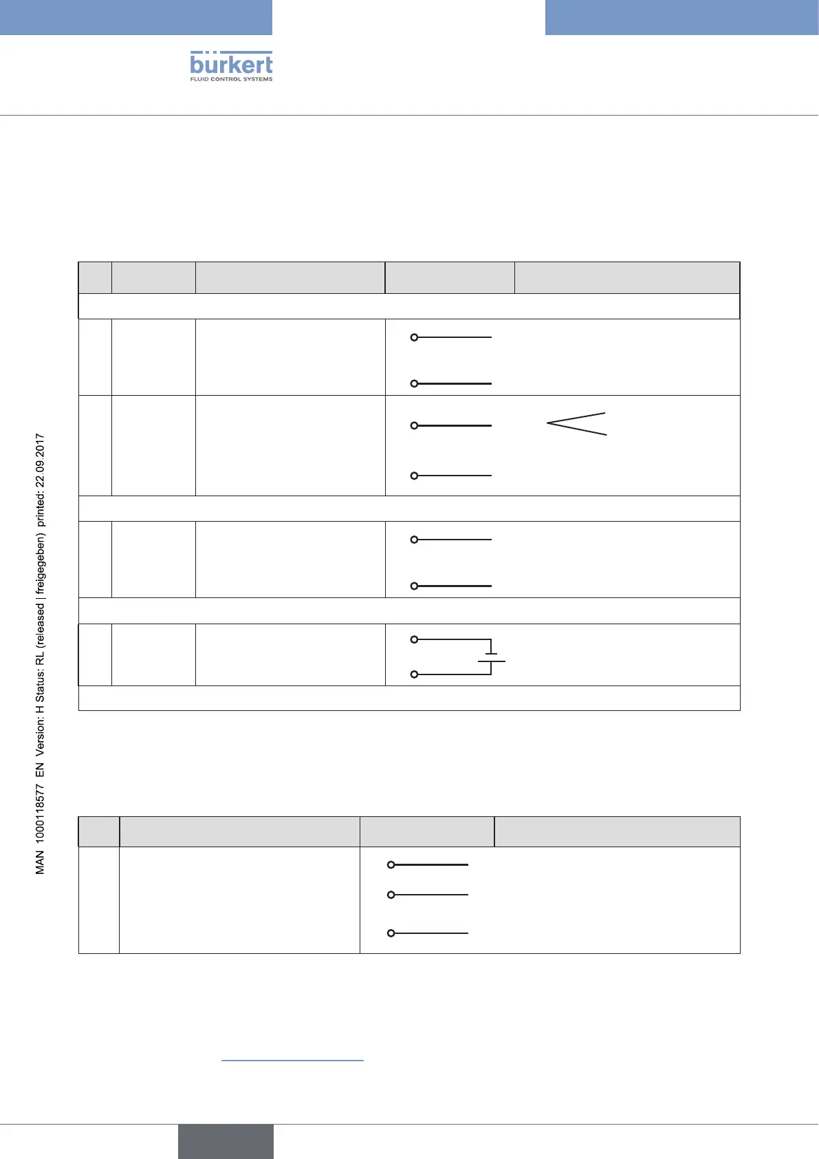
14.2.1. X1 - M12, 8-pole circular connector
Pin Wire colour* Configuration On the device side External circuit / Signal level
Input signals of the control centre (e.g. PLC)
1 white Set-point value
+ (0/4 – 20 mA or 0 – 5/10 V
1
+ (0/4 – 20 mA or 0 – 5 / 10 V)
completely galvanically isolated
2 brown Set-point value GND
2
GND set-point value
5 grey Binary input
5
+
0 – 5 V (log. 0)
10 – 30 V (log. 1)
6 pink Binary input GND
6
GND (identical with the GND
operating voltage)
Output signals to the control centre (e.g. PLC) - (only used for analog output option)
8 red Analogue feedback +
8
+ (0/4 – 20 mA or 0 – 5 / 10 V)
completely galvanically isolated
7 blue Analogue feedback GND
7
GND Analogue feedback
Operating voltage
3 green GND
3
24 V DC ± 10%
max. residual ripple 10%
4 yellow +24 V
4
* The indicated wire colours refer to the connection cable, part no. 919267, available as an accessory.
Table 14: Pin assignment; X1 - M12, 8-pole circular connector
14.2.2. X4 - M8, 4-pole socket (for binary outputs option only)
Output signals to the control centre (e.g. PLC)
Pin Configuration On the device side External circuit / Signal level
1 Binary output 1
1
0 – 24 V
2 Binary output 2
2
0 – 24 V
3 Binary output GND
3
GND (identical with the GND operating
voltage)
Table 15: Pin assignment; X4 - M8, 4-pole socket - output signals to the control centre
When the operating voltage is applied, the positioner is operating.
→ Now make the required basic settings and actuate the automatic adjustment of the positioner. The procedure is
described in chapter “21. Start-up sequence”.