55
Installation
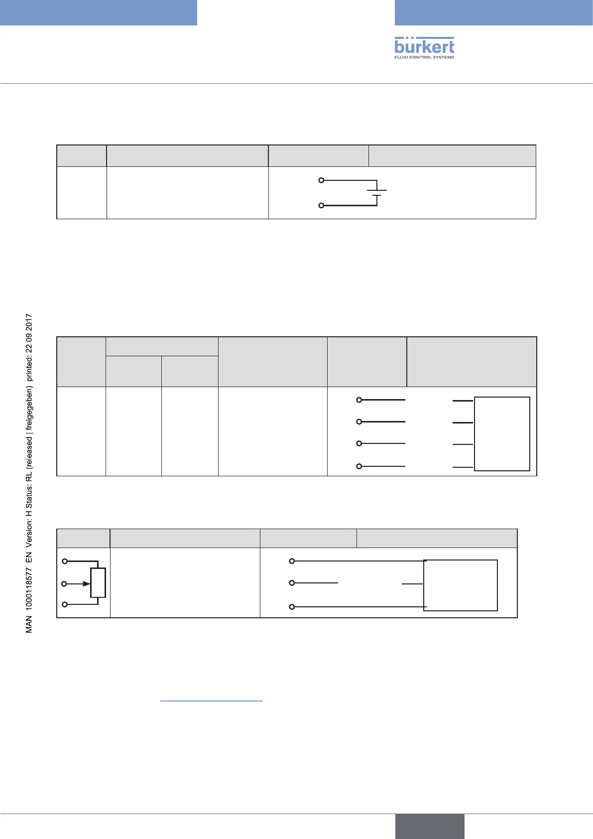
15.2.3. Operating voltage
Terminal Configuration On the device side External circuit / Signal level
+24 V Operating voltage +
+24 V
GND
24 V DC ± 10%
max. residual ripple 10%
GND Operating voltage GND
Table 19: Terminal configuration; operating voltage
15.2.4. Terminal assignment for external position sensor
(for remote model only)
Connection of the digital, contact-free position sensor Type 8798:
Terminal
Wire colour
Configuration
On the device
side
External circuit / Signal
level
Cable type
1
Cable type
2
S + brown brown Supply sensor +
S +
+
Remote
Sensor
Type 8798
digital
S - white black Supply sensor –
S –
–
A green red Serial interface, A-line
A
A-line
B yellow orange Serial interface, B-line
B
B-line
Table 20: Terminal assignment; digital, contact-free position sensor Type 8798
Connection of a potentiometric position sensor:
Terminal Configuration On the device side External circuit
Potentiometer 1
1
Potentiometer
Wiper 2
2
Wiper
Potentiometer 3
3
Table 21: Terminal assignment; potentiometric position sensor
When the operating voltage is applied, the positioner is operating.
→ Now make the required basic settings and actuate the automatic adjustment of the positioner. The procedure is
described in chapter “21. Start-up sequence” .