56
Installation
15.3. Terminal assignment for cable gland - process
controller Type 8793
→ First connect the process controller as described in chapter “15.2. Terminal assignment for cable gland -
positioner Type 8792”
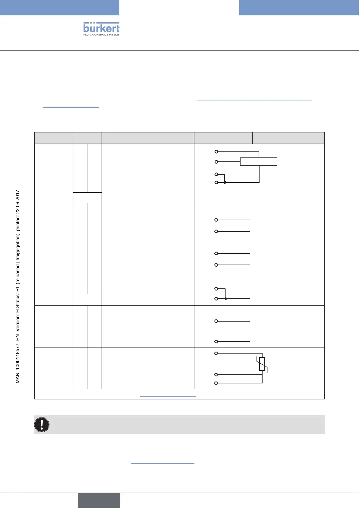
15.3.1. Terminal assignments of the process actual value input
Input type* Terminal Configuration On the device side External circuit
4 – 20 mA
- internally
supplied
actual value
1 +24 V transmitter input
1
2
3
GND
Transmitter
GND
2 Output from transmitter
3 Bridge to GND (Terminal GND
from operating voltage)
4 not used
GND GND from operating voltage
4 – 20 mA
- externally
supplied
actual value
1 not used
2 Process actual + 2
+ (4 – 20 mA)
3 Process actual – 3 GND 4 – 20 mA
4 not used
Frequency
- internally
supplied
actual value
1 +24 V sensor supply 1 +24 V
2 Clock input + 2 Clock +
3 not used
4 Clock input – 4
GND GND from operating voltage GND Clock – (GND)
Frequency
- externally
supplied
actual value
1 not used
2 Clock input + 2
Clock +
3 not used
4 Clock input – 4
Clock –
Pt 100
(see infor-
mation
below)
actual value
1 not used
2
3
4
Pt 100
2 Process actual 1 (Power supply)
3 Process actual 3 (GND)
4 Process actual 2 (Compensation)
* Can be adjusted via software (see chapter“21. Start-up sequence”).
Table 22: Terminal assignments of the process actual value input
Connect the Pt 100 sensor via 3 cables for cable compensation reasons.
It is essential to bridge terminal 3 and terminal 4 on the sensor.
When the operating voltage is applied, the process controller is operating.
→ Now make the required basic settings and actuate the automatic adjustment of the process controller. The
procedure is described in chapter “21. Start-up sequence”.