4
1. Setup
a. Robot and Net Assembly
b. Power Supply (Input: 100 – 240 V, Output: 24V DC, 2.7A)
c. Tablet
d. Tablet Cable
e. Tablet Power Supply
f. Control Panel Bracket
g. Remote Switch Fob
h. Plug Adapter (if applicable)
Other parts: Hex wrenches (2 and 4 mm) for wheels, Wheel Ad-
justment Gauge (black tube with fins), spare rubber bands for Side
Nets, Velcro strips. Repair White Strips for repair of Deflector Plate.
1. Place the robot on top of your table tennis table. Fold apart
both sides of the net at the same time until the first stop (Photo
1A). Rotate towards you the curved Support Legs into the posi-
tion as seen in Photo 1B (about 15–20 cm, or 6–8 in. apart).
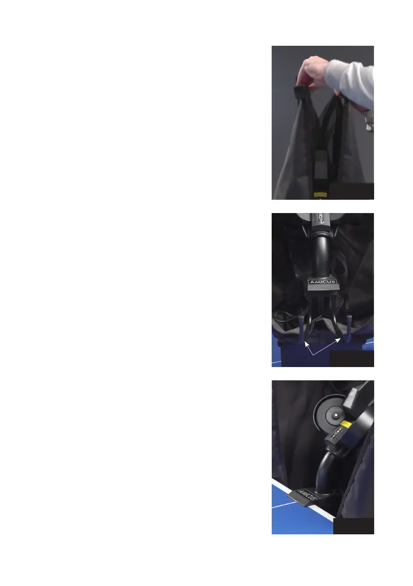
2. Rotate the entire robot 180° with the Support Legs facing away
from you. From behind, grasp the robot with both hands on the
bottom of the Base. Pick up the robot, angle the Support Legs
downward, slip them under the end of your table, and push the
robot onto the end of the table. Gently let go of the base and
the robot will hang by its own weight as seen in Photo 2.
Please note that Amicus robots can fit tables with tops 9 mm to
25 mm thick. To adjust, unscrew the rubber tip on each Support
Leg by an amount equal to the difference between 25 mm and
the thickness of your tabletop. E.g., if your tabletop is 19 mm
thick, you will need to unscrew each rubber tip 6 mm (25 mm–
19 mm). When correctly adjusted, your robot should be level and
plumb (vertical). Occasionally the screw underneath the rubber
tip becomes stuck. To free, remove the rubber tip and turn the
screw with a hex wrench or pair of pliers.
CAUTION: Please use the included longest Velcro strip to help
secure the robot to the end of the table. This is especially im-
portant if children play around the table. The Velcro strip helps
stabilize the robot to prevent it being knocked off the table.
3. Loosen the large Black Knob found on the rear of the Ball Tube.
Rotate the head 180° and then pull the head upwards until the
3
rd
coloured ring on the tube is just visible (Photo 3A), then
tighten the Black Knob to hold it in place (but not too tightly).
Lastly, fasten the Head Cable coming from the head to the serial
connector found on top of the Base (Photo 3B).
Photo 1A
Photo 1B
Photo 2
Support Legs