iNetVu™ Service Manual Page 66 of 109
6)
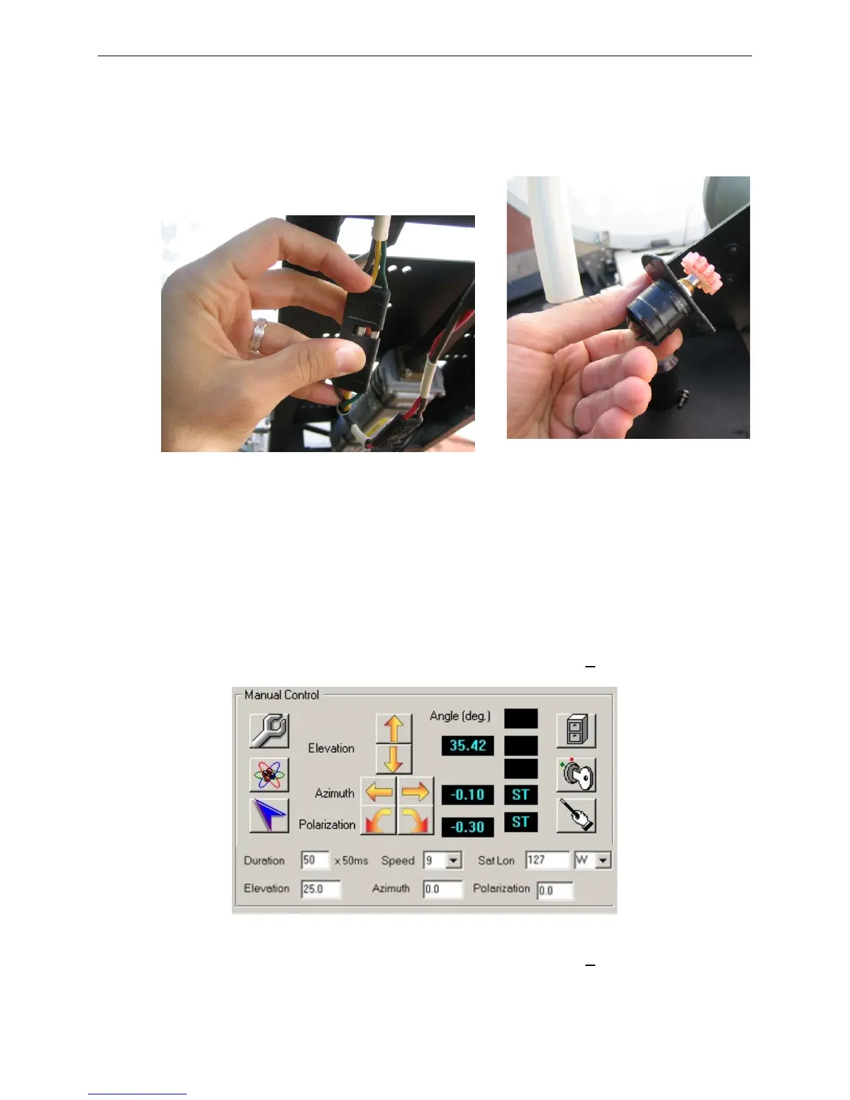
Connect potentiometer connectors, apply grease to the gearing, and insert new
potentiometer into the opening and secure, but do not tighten. Ensure the labels
match on the potentiometer cable and the internal harness cable.
Fig. 23: Wire connectors (left) and Polarization Potentiometer for A1200 (right)
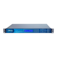
7)
To verify functionality:
a. Power on the system and start iNetVu™ Mobile Software.
b. Go to Advanced Controls.
c. Ensure that there are no red indicators flashing.
d. Verify that the Polarization Angle is approximately 0 + 10.
Fig. 24: Manual Controls
VI. If the Polarization Angle is not approximately 0 + 10, switch to
CONFIG mode.