iNetVu™ Service Manual Page 72 of 109
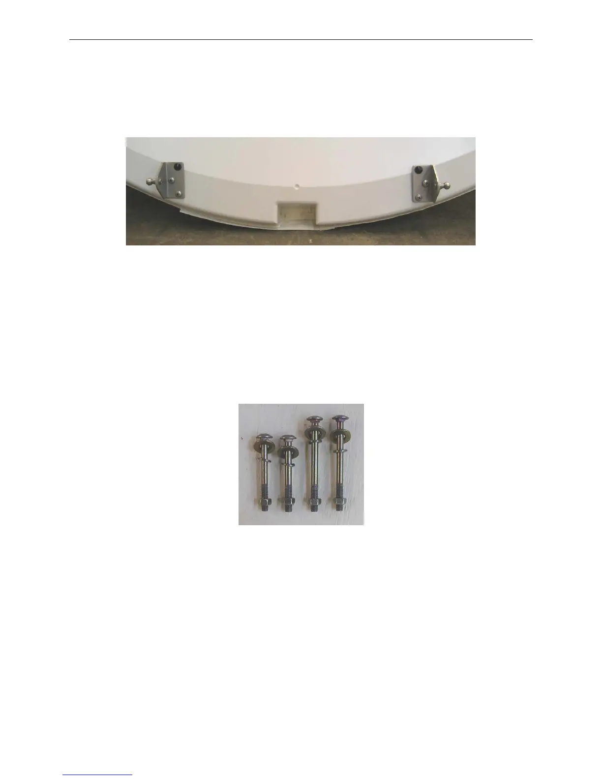
a. Ensure that the Ball Joint Stud faces outwards (away from the centre of
the Reflector) and that the black button faces the top.
b. Insert and tighten the two (2) lower screws.
Fig. 30: Correct Gas Spring Bracket Orientation
5)
Re-attach the Reflector Back Cover to the Reflector, leaving the strap at the
bottom open.
6) Carefully place the reflector onto the Mobile Platform. Ensure that the Reflector
Support Bracket at the base of the Elevation Arm fits into the groove at the base
of the Reflector.
7) There are four (4) carriage bolts included in the Reflector Assembly Kit.
Fig. 31: Carriage Bolts