ENGINEERING MANUAL • Approved Document No. DFU5010000 Rev 4 • Page 13 of 48
CAST XFP 16 ZONE ANALOGUE ADDRESSABLE FIRE ALARM PANEL
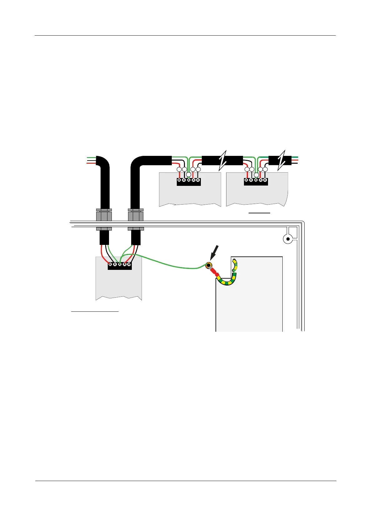
Fig.12 : Typical network wiring
ABCAB
A B A B
A
B B
TO NEXT
NETWORKED
PANEL
(IF REQUIRED)
TO NEXT
NETWORKED
PANEL
(IF REQUIRED)
POWER SUPPLY
PCB
Base Earth Distribution Post
C
C
A
MAXIMUM NETWORK LENGTH = 1KM
PANEL 2
NETWORK DRIVER CARD
(XFP761)
PANEL N
NETWORK DRIVER CARD
(XFP761)
PANEL 1
NETWORK DRIVER
CARD
(XFP761)
FOR OTHER NETWORKED PANELS DO NOT CONNECT
SCREENS TO THE BASE EARTH DISTRIBUTION POST
AT ONE PANEL ONLY CONNECT SCREEN TO THE BASE
EARTH DISTRIBUTION POST (PANEL 1 SHOWN ABOVE)
At each network driver card, connect A to A, B to B and terminate incoming and outgoing screens to
terminal C only as shown below.
At ONE network driver card, connect A to A, B to B and terminate screens to the panel’s base earth
distribution post as shown below.
The network wiring should be installed to meet BS 5839: Part 1 and BS 7671 (Wiring Regulations) and/
or other national standards of installation where pertinent - see ‘cable types & limitations’, page 3.
It is recommended that 2-core screened, enhanced fire-resistant cable ≥1 mm
2
is used for network wiring.
 Loading...