Functional checks (Continued)
5. Fill with room temperature water to the Heating water line.
6. Plug the T/Pump
®
Temperature Therapy Pump into a properly grounded Hospital Grade receptacle.
Notes
• The T/Pump
®
Temperature Therapy Pump performs a self test of the lights and audible alarm, with light pattern and
short audible beep.
• The T/Pump
®
Temperature Therapy Pump goes to Standby mode with only the Standby light on.
7. Press the On/Standby button.
8. Set the temperature to 107° F (42°C) and select Continuous Therapy Mode.
9. Allow the temperature to stabilize. Stabilization is indicated by a steady (not ashing ) light at the temperature setpoint.
10. After stabilization, allow 5 minutes before proceeding. The T/Pump
®
Temperature Therapy Pump controls to 107° F ± 2° F
(42° C ± 1°C) at the inlet to the pad for the duration of the test.
11. On the TPT9, take a temperature reading every 1/2 minute for 5 minutes, average the 10 readings and record the ow
reading from the TPT9. Verify the average temperature is at 107° F ± 2° F (42° C ± 1°C) and ow is 7 gph (26.5 lph) minimum.
Notes
• If the T/Pump
®
Temperature Therapy Pump does not reach the temperature and ow, press the On/Standby button,
unplug the unit, check the pad and hoses for kinks and start over.
12. Press the On/Standby button and unplug the unit.
Notes
• If at any time the Function test needs to be stopped, press the On/Standby button.
Backup limit thermostat test
This test is to make sure that the pad stays below a safe level in an over temperature condition.
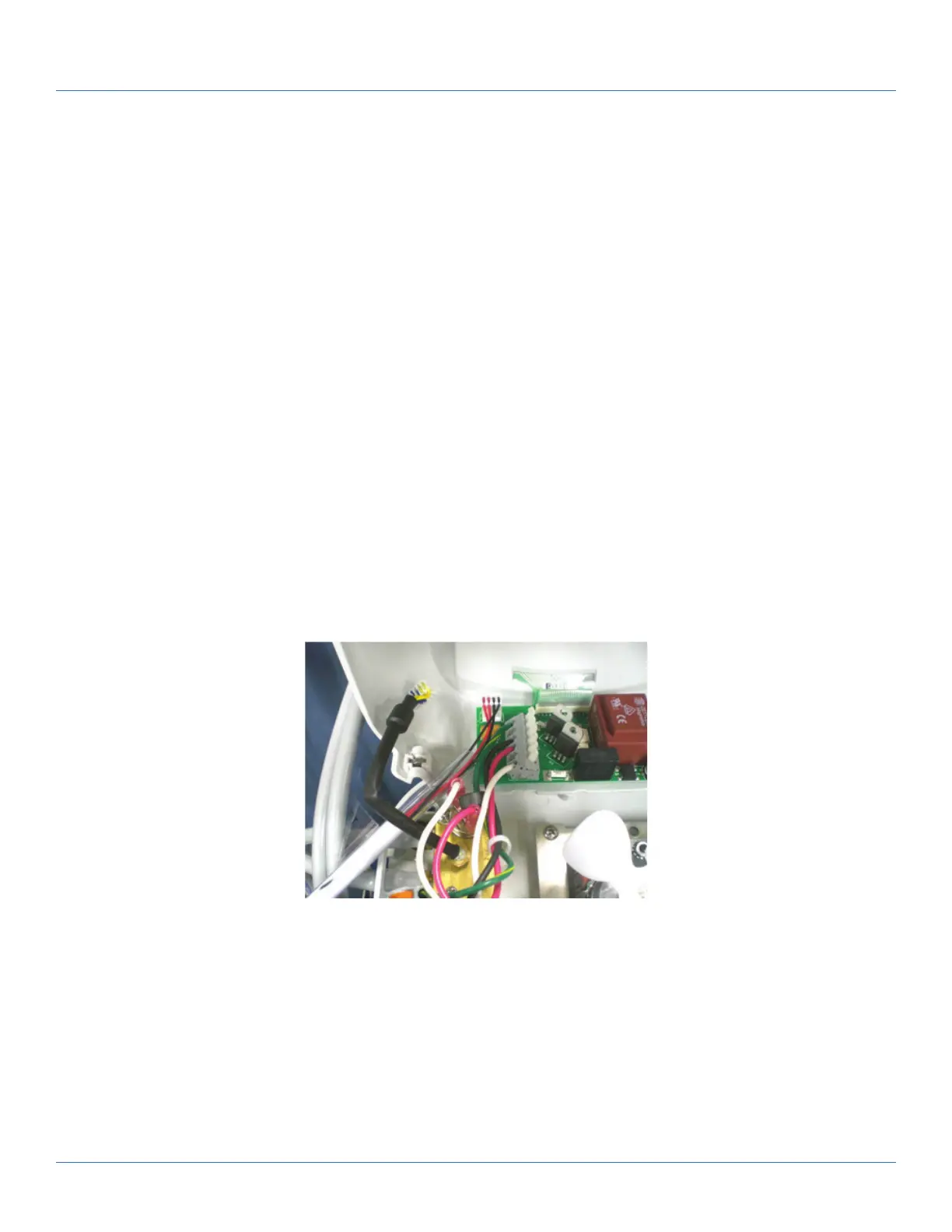
Figure 3: Connection of test temperature sensor
1. Unplug the product.
2. Using a #2 Phillips screwdriver, remove and save the 9 screws that secure the tray to the reservoir.
P/N 90018082 (x4) P/N 90018075 (x5)
3. Unplug the Temperature Sensor.
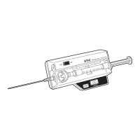
4. Install the test probe (Figure 3 on page 18). Make sure that you position the test probe away from the motor fan.
101176 Rev 1
Preventive maintenance
18 c2dx.com