73
Serviceanleitung / Service Manual / / /
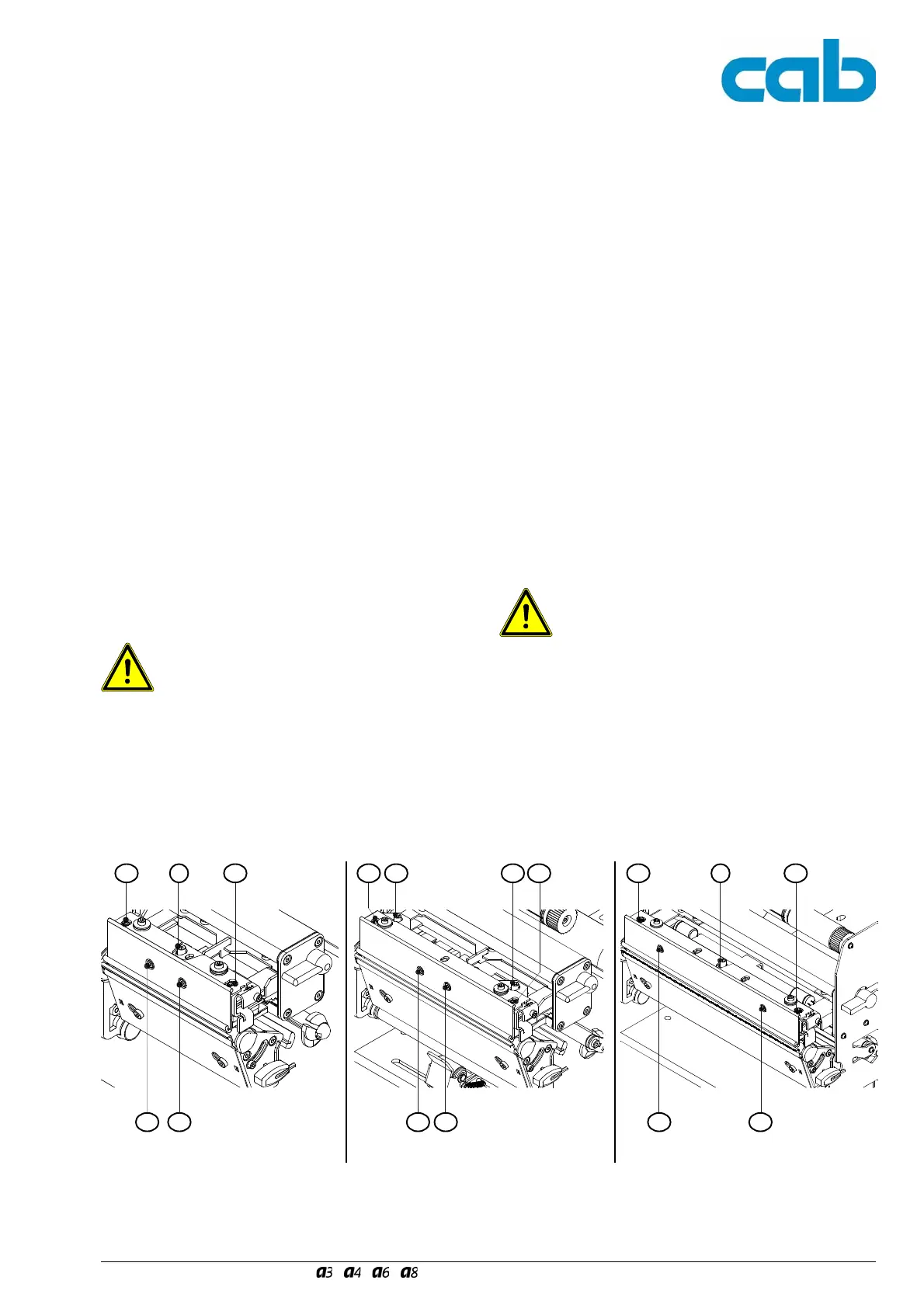
2 - Justageschrauben zur Einstellung des Kopf-
andrucks
-(2a) wirkt auf die innere, (2b) auf die äußere Druck-
kopfhälfte.
- Drehen im Uhrzeigersinn erhöht den Kopfandruck auf
der entsprechenden Seite. Drehen entgegen dem
Uhrzeigersinn verringert den Kopfandruck.
Eine Erhöhung des Kopfandrucks an der Innenseite mit der
Schraube (2a) führt zu einer Verbesserung der Druckbild-
schwärzung auf dieser Seite und zu einer Verschiebung des
Transferfolienlaufs nach außen. Eine Erhöhung des Kopfan-
drucks mit der Schraube (2b) führt analog zu einer Verbes-
serung der Druckbildschwärzung auf der Außenseite und zu
einer Verschiebung des Folienlaufs nach innen.
3 - Schrauben zur Druckkopfbefestigung
- Durch Drehen entgegen dem Uhrzeigersinn wird der
Druckkopf von der Druckkopfhalterung gelöst.
Für Justagearbeiten zur horizontalen Ausrichtung des
Druckkopfes mit den Justageschrauben (1a und 1b) ist die
Schraube (3) zur Druckkopfbefestigung um eine Viertelum-
drehung zu lösen. Beim A6 sind zwei Schrauben (3a und
3b) zu lösen.
Nur dann lässt sich der Druckkopf zur Druckkopfhalterung
verschieben.
Sachschäden!
Der Versuch einer Justage bei angezogener
Befestigungsschraube (3) bzw.
bei A6 angezogenen Schrauben (3a und 3b)
kann zu Defekten an der Kopfbaugruppe
führen.
Ziehen Sie nach Beendigung der Justage die Schraube (3)
bzw. bei A6 die Schrauben (3a und 3b) an. Erst danach ist
eine echte Druckbildbewertung möglich.
Bild 54 Justage der Druckmechanik I Fig. 54 Adjusting the Print Mechanism I
1a 1b
2a 3 2b
2 - Screws for adjusting the printhead pressure
-(2a) mainly effects the inner side of the printhead, (2b)
mainly effects the outer side
- Turning the screws clockwise will increase the print-
head pressure on the corresponding side. Turning the
screws counter-clockwise will decrease the printhead
pressure.
By turning screw (2a) and thereby increasing the printhead
pressure, the print image will darken at the inner side and
the transfer ribbon feed will shift outwards.
By turning screw (2b) and thereby increasing the printhead
pressure, the print image will darken at the outer side and
the transfer ribbon feed will shift inwards.
3 - Printhead locking screws
- Turning the screw counter-clockwise will loosen the
printhead from the printhead carriage.
For horizontal alignment of the printhead using the screws
(1a and 1b), the screw (3) must be loosened by a quarter-
turn. For A6 you have to loosen two screws (3a and 3b).
This allows shifting the printhead.
Material damage!
Turning the screws (1a and 1b) while the
printhead is fastened with the printhead
locking screw (3) respectively
for A6 screws (3a and 3b)
may cause damage to the printhead carriage.
Once the adjustment is completed, fasten the screw (3)
respectively for A6 the screws (3a and 3b). Only then a real
assessement of the print image quality can be done.
1a 1b 1a 1b
2a 3 2b2a 2b3a 3b
A3, A4 A6 A8