21
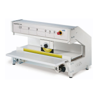
5.8. Contrôle du réglage des couteaux
Lors de la première utilisation, après un dé-
placement de la machine ou un remplacement
descouteaux,ilestrecommandédevérier
leréglageetlapositiondescouteauxl’unpar
rapport à l’autre. Dans ce but, nous proposons
un comparateur (N° d’article 8970208), instru-
mentdemesureservantàlavérication,vendu
en option.
Tourner le levier de blocage (17) dans la
position "a". Le moteur est ainsi débrayé du
couteau supérieur (20).
Pousser le support du couteau supérieur (20)
jusqu’aumilieudubâti.
Fixerlecomparateursurlesupportdu
Couteau supérieur à l’aide de la vis (29) dans
leletage(27)prévuàceteffet.Bienvérier
que le picot (30) se trouvant sur le manche
(31) entre dans le trou (28) sur le support.
Lever le levier (31) de sorte que la pointe du
comparateur (32) vienne s'appuyer sur le
couteau supérieur (23) à 2 mm du bord de
couteau. Tourner la molette du comparateur
jusqu’à ce que l’aiguille indique le „0“ sur le
cadran divisé au 1/100 mm.
Baisser le levier (31) de sorte que la pointe
du comparateur (32) vienne s'appuyer sur
le couteau inférieur (24) à 2 mm du bord de
couteau. La valeur ainsi mesurée ne doit
varier lors du déplacement du support du
couteau supérieur (20) sur la longueur du
couteauinférieurquedemaximum+/-0,1
mm par rapport à la valeur observée sur le
couteau supérieur.
Sil’écartmesuréentrelescouteauxest
supérieur à +/- 0,1 mm, il faut en informer la
société compétente pour que des mesures
soient prises pour une réparation éventuelle.
Mettre le levier de blocage (17) dans la posi-
tion "b", de manière à ré-embrayer le moteur
au couteau supérieur.
1.
2.
3.
4.
5.
6.
7.
5.8. Check the Blade Alignment
When the machine is put into operation for the
rsttime,orfollowingamoveofequipmentora
change of blades, it is advantageous to re-check
the alignment of the blades in relationship to one
another. For this purpose a dial gauge assembly
(Part No. 8970208) is available as an option.
Move the lever (17) to the position 'a'.
The motor drive to the blade carrier (20) is
now disconnected.
Move the blade carrier (20) to the middle of
its range of travel.
Afxthedialgaugeassemblyontothe
threaded hole (27) in the blade carrier and
screw tight with the knurled screw (29)
provided.
Ensure that the small spigot (30) mounted on
the inside of the lever (31) locates correctly
into the hole (28) provided in the blade car-
rier.
Swing the lever (31) upwards until the tip of
the gauge feeler (32) presses onto the upper
blade (23) at 2 mm of the edge of the blade.
Rotate the scale on the dial gauge until the
pointer in the 1/100mm division is lined up
with the „0“ on the scale.
Swing the lever (31) downwards until the tip
of the gauge feeler (32) presses onto the
lower blade (24) at 2 mm of the edge of the
blade. The results achieved from measuring
along the complete length of the lower blade
may not vary by more than ±0.1mm from
the values obtained from the upper blade
measurements.
In the event of the values obtained by the
above procedure being greater than ±0.1
mm, the servicing agent responsible for your
machine should be contacted.
Move the lever (17) to the position 'b'.
The motor drive to the blade carrier (20) is
now reconnected.
1.
2.
3.
4.
5.
6.
7.