PRELIMINARY
Document type: Title: Revision date: Revision:
User's Manual (MUT) Mod. V1729 4 Channel 12 Bit Sampling ADC 22/06/2005 3
NPO: Filename: Number of pages: Page:
00109/04:V1729.MUTx/03 V1729_REV3.DOC 38 23
4.5 Mechanical and electrical standards
4.5.1 Mechanical standard
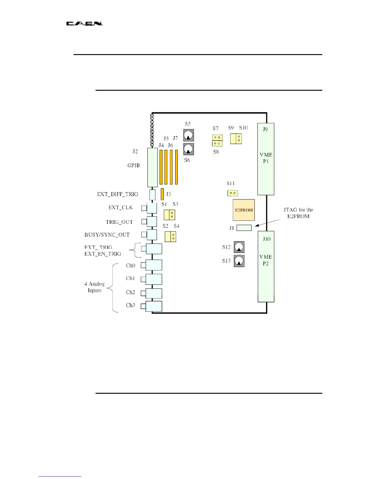
Fig. 4.2: implementation of the connectors and configuration elements on the V1729
The V1729 board is of VME 6U mechanical format. The two connectors P1 and P2 of the
VME crate are usable, both for the supply and the VME dialogue. However, these boards
can completely be accessed via the GPIB bus out of a VME crate, or by only using the
latter as mechanical and power supply support.
The plugs used for all the digital inputs/outputs are of female LEMO type. The analog
inputs are in double LEMO.
4.5.2 Electrical interfaces
The V1729 board is compatible with two acquisition buses :