PRELIMINARY
Document type: Title: Revision date: Revision:
User's Manual (MUT) Mod. V1729 4 Channel 12 Bit Sampling ADC 22/06/2005 3
NPO: Filename: Number of pages: Page:
00109/04:V1729.MUTx/03 V1729_REV3.DOC 38 35
4.9 Synopsis of the board
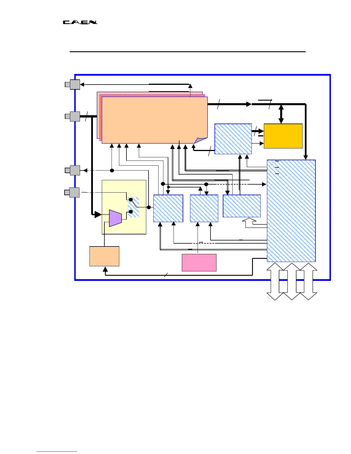
Fig. 4.3: synopsis of the V1729 board
The architecture of the V1729 board (Fig 4.3) is modulary. This architecture as well as
the components used were selected so as to minimize the costs of conception and
production of the board. The board is principally made up of six blocks :
The 4 channels of acquisition and fast digitization (synopsis of a channel in Fig 4.4).
The management of the trigger.
The management of the clocks.
The slower readout of the MATACQ chips.
The management of writing and of re-reading the digital memory (RAM).
The interfacing with the acquisition system.
The last four blocks (except the RAM itself) as well as the digital part of the trigger
system are integrated in a single programmable component (FPGA). This considerably
reduces the costs of production and will permit an easy upgrading of the system in the
future.
External
trigger
Busy/
Sync_Out
RAM
64k*16bits
1.1.1.2 ADC
RAM
MANAGER
4
Oscillator
100MHz
DAC
thresh
8 canaux
8 canaux
4 channels
1.1.1.3 Output : Bus