PRELIMINARY
Document type: Title: Revision date: Revision:
User's Manual (MUT) Mod. V1729 4 Channel 12 Bit Sampling ADC 22/06/2005 3
NPO: Filename: Number of pages: Page:
00109/04:V1729.MUTx/03 V1729_REV3.DOC 38 9
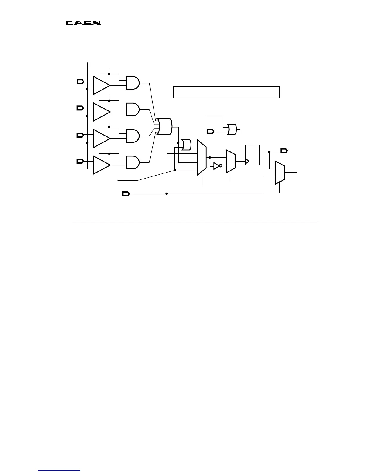
Fig. 2.3: simplified description of the trigger selection chain
2.2 Validation of the trigger by a second subsequent signal.
In the case where one would like to validate the data stored in the MATACQ chips before
their transfer towards the RAM, it is possible to make use of the EXT_EN_TRIG input to
introduce therethrough a validation signal (see figure 3c). This is particularly useful if the
system produces such a signal with a delay greater than the maximum sampling depth
(2560/Fp i-e 1.25μs at 2GS/s and 2.5μs at 1GS/s) and smaller than the transfer time
towards the RAM (650μs). This can thus permit a big decrease of the potential dead-time
linked to the readout. In this case, the usual use of the EXT_EN_TRIG signal (which
permits inhibiting the trigger as described on figure 3b) is inhibited.
In order to perform the validation, a programmable 8-bit latency counter ( called
POST_STOP_LATENCY) with steps of 2.5μs is started at the end of the POSTTRIG,
and if the external validation signal hasn’t arrived before the end of that delay, the
Matacq chips switch back into the analog input signal writing mode thus waiting for the
next trigger. If on the other hand the validation signal did arrive, the waiting data is
digitized then stored into the RAM. This mode is validated thanks to the bit 5 of the
TRIGGER_TYPE register (see IV.4). Moreover, a second 8-bit register ( called
POST_LATENCY_PRETRIG) with the same steps of 2.5μs permits the programming of
the time to wait before enabling the trigger again if the validation didn’t occur. The
minimum time for refilling is of 1.25μs at 2GS/s and of 2.5μs at 1GS/s. The minimum
value in that register is thus 1.
TRIGA
Ch0
Ch1
Ch2
Ch3
DAC threshold
TRIG enable
Select
Select
Select
TRIG_OUT
TRIG_AUTO