PRELIMINARY
Document type: Title: Revision date: Revision:
User's Manual (MUT) Mod. V1729 4 Channel 12 Bit Sampling ADC 22/06/2005 3
NPO: Filename: Number of pages: Page:
00109/04:V1729.MUTx/03 V1729_REV3.DOC 38 24
- VME via the P1 connector of the VME (plus the P2 for the A32/D32 mode), 96 pin male
connector DIN 41612 .
- GPIB via the HE10 connector located on the front panel (26 points male).
This board has an address coded over 8 or 16 bits, configurable through a set of
hexadecimal rotary switches. For the GPIB and the VME A24/D16, one uses only the two
rotary switches S5 and S6. For the VME A32/D32, one must also use the two rotary
switches S10 and S11.
In GPIB, the address is configurable from 1 to 29 (decimal).
In VME, the address is configurable from h01 to hFF on the bits 16 to 23 for the A24/D16
mode, and from h0001 to hFFFF on the bits 16 to 31 for the A32/D32 mode.
The choice of the type of interface is determined by the S9 jumper. By default (without
jumper), the bus used is the VME. When the jumper is mounted, it is the GPIB which is
used.
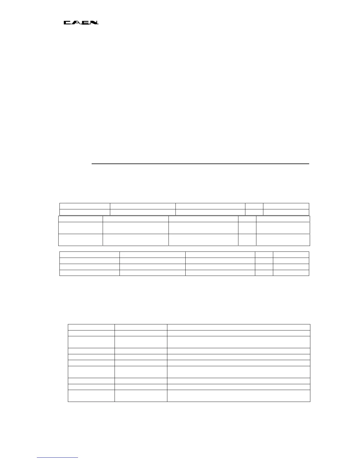
4.5.3 Summary of front panel signals
The fast logical signals of input “EXT_TRIG” and of output “BUSY/SYNC_OUT” and
“TRIG_OUT” of the V1729 board use the NIM standard (-16mA in 50 Ohms for the
logical state « 1 », no current for the logical state « 0 »).
EXT_EN_TRIG External Trigger Enable Half double LEMO I NIM
EXT_TRIG External Trigger Half double LEMO I NIM
EXT_DIFF_TRIG External Trigger Double pin I DIFF ECL
EXT_CLK External clock LEMO I NIM
TRIG_OUT Trigger Output LEMO O NIM
BUSY/SYNC_OUT Busy/Synchro Output LEMO O NIM
The front panel leds permit having an image of the current status of the board. The green
ones shows the presence of the external power supplies ; the yellow ones that of the
supplies realized on the board by the regulators. Finally, the red ones are linked to the
internal signals via monostables which permit the visualization of very short pulses and to
digital gates for the continuous levels.
Name Type Function
VME Monostable + gate VME access acknowledged by the board.
GPIB Monostable + gate GPIB access acknowledged. Remains ON if no EOI is sent by the
controller at the end of a writing sequence.
SPECS Monostable + gate SPECS access acknowledged.
RESET Monostable + gate Board reset.
CLOCK Monostable only The Altera FPGA is providing the main clock to the board.
ACQRUNNING Monostable + gate Is set ON after a “start acquisition” command. Is set OFF at the end of
the POSTTRIG.
TRIG Monostable + gate Image of the TRIGA signal.
WR-RAM Monostable + gate Write access to the data RAM.
INTERRUPT Monostable + gate Displays the INTERRUPT signal which is produced at the end of the
acquisition sequence.
Name Purpose Connector I/O TYPE
IN0+ to
IN3 +
Positive Analog Inputs Half double LEMO
or SMA
I 50Ohm terminated
IN0- to
IN3 -
Negative
Analog Inputs (option)
Half double LEMO I 50Ohm terminated