Using Sentinel
CX3001 v7.0 © Calnex Solutions 22
Each installed channel (A to F depending on modules fitted) is displayed on a line with the following columns:
Drop-down list for selection of the type of input signal, including:
• Standard signal types predefined in the instrument
• Signal types defined manually (refer to the "Signals" menu below).
Trigger level
Cable comp.
2
1 PPS converter
2
Within the limit ± 5V
Value up to 1000ns to compensate for delay introduced by the length of
cable. (1 PPS signal only)
Drop down list to select if Calnex converter box is being used to convert
balanced 1 PPS to single ended 1 PPS. When enabled, this will
automatically compensate for the delays introduced by that device.
Drop-down list defining the trigger slope: Positive or Negative
Drop-down list defining the channel impedance, 75 or 1M
Drop-down list (
ON/OFF
) for application of a predefined RC-type analogue
LP filter with a cut-off frequency of approximately 10kHz and signal
rejection of 13dB at 1MHz. This filter is used to suppress noise on 1 PPS
signal measurements
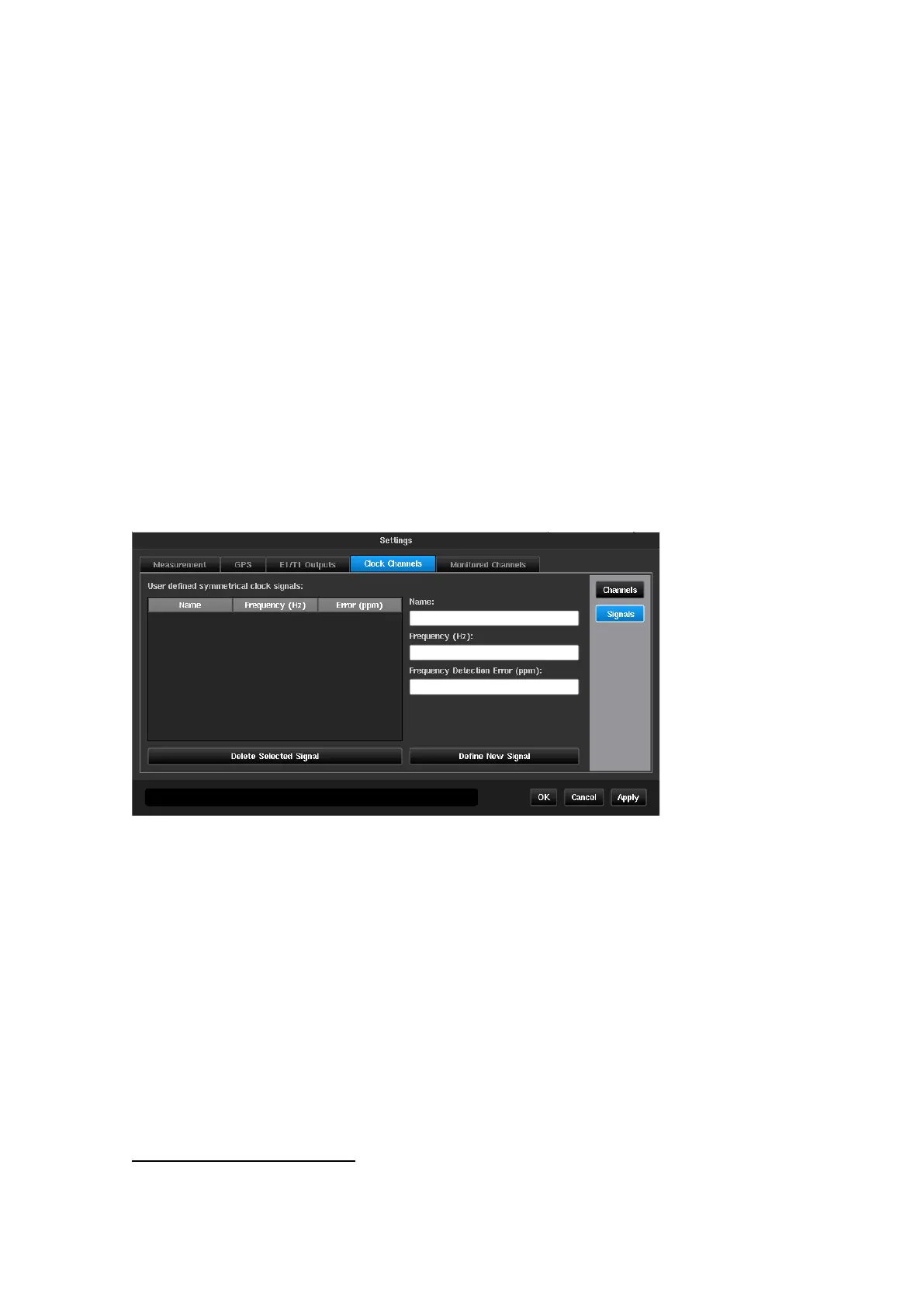
Signals
The Signals screen is used to define the input signals not included in the predefined list in the instrument. Only
clock type signals can be defined in this menu.
On the left the signals already defined manually are listed. A signal can be deleted by selecting it (highlighted)
then pressing the Delete selected signal button.
The fields on the right are used to define a new signal type, by entry using the virtual keyboard.
The accepted values are those measurable by the
instrument, i.e. 1 PPS/2s to 200MHz
Frequency Detection Error
Tolerance in ppm on the frequency detected by the
system during the signal check. If the measured signal is
out of tolerance, a signal unknown message is
displayed as result of the signal check
Signal types shown in Appendix A
2
These items will be greyed out if Settings->Measurement->Common TIE Mode is not set to
TIE + 1 PPS
TE
or the signal type is not 1 PPS
 Loading...