Interlock
All units have interlock circuit incorporated in control circuit, brought out
to two terminals. These terminals are shorted out for factory testing.
The interlock may be used to control e heatpump from a remote
location or a built in flow switch.
On site shorting loop is to be removed and two wires taken to pair of
volt free contacts in water pump starter/contactor/relay or flow switch
so at e heat pump cannot operate unless water pump is operating
(see figs 5 and 6).
Fig. 5
RECOMMENDED ELECTRICAL INSTALLATION FOR CALOREX HEAT PUMP
WITH SINGLE PHASE WATER PUMP.
L
N
WATER PUMP
MORE THAN 3/4 HP
SINGLE PHASE
SINGLE PHASE
SUPPLY TO SUIT
CAPACITY OF
WATER PUMP
L
N
L N
L
N L
4 POLE N/O STARTER WITH
OVERLOAD AND 230V 50Hz
COIL RATED TO SUIT
WATER PUMP
N
L1
L2 L3 N
5
INTERLOCK
CALOREX HEAT PUMP
THREE PHASE
1
2
3
4
7
6
SWITCHED FUSE ISOLATOR WITHIN
2m OF HEAT PUMP AND SIZED IN
ACCORDANCE WITH DATA SHEET
9
8
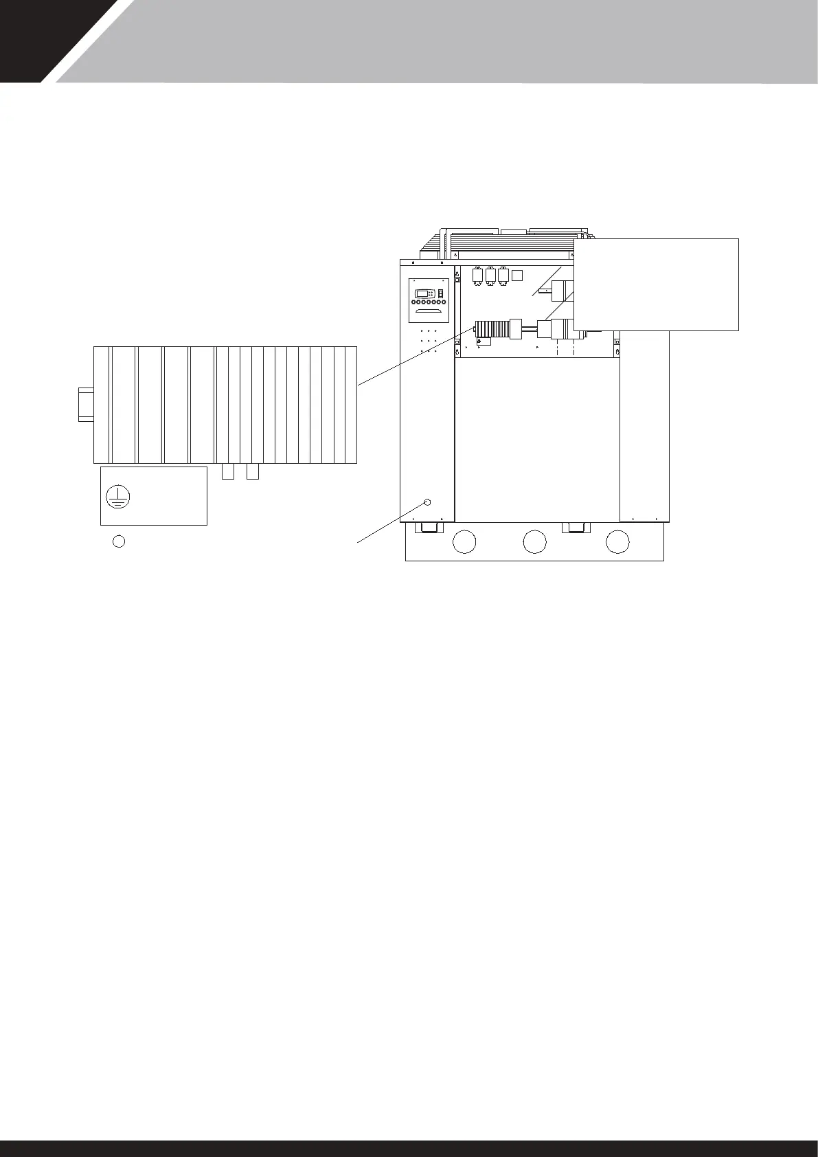
Fig. 4
LOCATION OF MAINS INPUT AND EXTERNAL INTERLOCK TERMINALS
N L1 L2 L3
D209450 ISS 1
1 2 3 4 5 6 7 8 9
10
11
12
13
14
15
16
17
SOFT
START
STARTER
OR
EXTERNAL
FLOW
SWITCH
R1 R2 R3
N L1 L2 L3
D209450 ISS 1
MAINS SUPPLY IN
RUN
STANDBY
TEMP
OKHEAT FAULT CHILL DEFROST MAINS
CHILL
LIMIT
WATER
TEMP
REMOVE SERVICE PANEL
(1/4 TURN FASTENERS)
15
SD566250 ISSUE 35