184
254
U V W X Y E
L N
24V 12V 0 CT L2T L1T
11 10 ES ES
p. 5 - Manual FA0 0 679 - EN v. 1- 12/2017 - © CAME S.p.A. - The contents of this manual may be changed, at any time, and without notice.
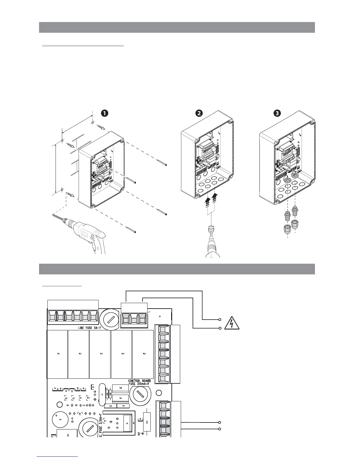
ELECTRICAL CONNECTIONS
Input voltage
INSTALLATION
Fastening the control panel
Fasten the control panel in a protected area using suitable screws and dowels .
Only use 6 x 70 mm cylinder-head screws.
Drill through the pre-drilled holes (18 and 20 mm) under the control panel's base .
⚠
Be careful not to damage the control board.
Enter the cable gland with the corrugated tubes for threading the electrical cables .
120 V or 230 V AC - 50/60 Hz
Accessories 24 V AC - max 20
W power-supply output