B
A
450
120°
B
450
A
19
150
450
WVU
XVUYW
Manual FA01175-EN - 05/2018 - © CAME S.p.A. - The contents of this manual may change, at any time, and without notice.
-
Translated original instructions
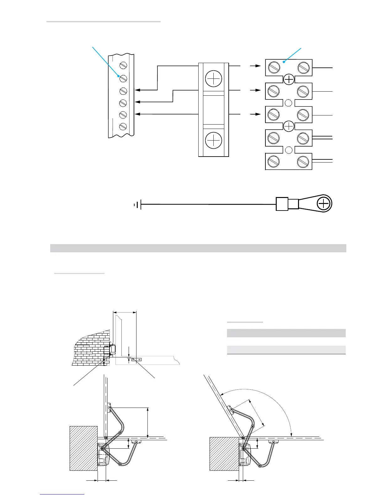
Securing the brackets
N.B. the drawings refer to installation of the left-hand gearmotor. The installation of the right-hand gearmotor is symmetrical.
Determine the fixing point for the gate bracket and calculate the fixing point of the pillar bracket, respecting the values shown in the drawings
and table.
Gate bra-
cket
Pillar bra-
cket
INSTALLING AND CONNECTIONS FOR OUTWARD-OPENINGS
Below are the only procedures that vary compared to standard installations:
Application size
Leaf opening A B
90° 150
0 120
120° 150
0 60
Connecting to the ZA3N/ZF1N/ZM3E control panel
Motor 1: U - V - W
Motor 2: X - Y - W
Motor terminals
Control panel terminal board
Ground
If only using one motor, such as with one-leaf gates, connect it to W X Y (M2) regardless of which side it is installed on.