UNI5931 M8x20
UNI5931 M8x12
UNI5931 M8x20
UNI6954 Ø 2.9x13
p.
9 - Manual code:
FA01030-EN v.
1- 01/2018 - © Came S.p.A. - The manual's contents may be edited at any time without notice.
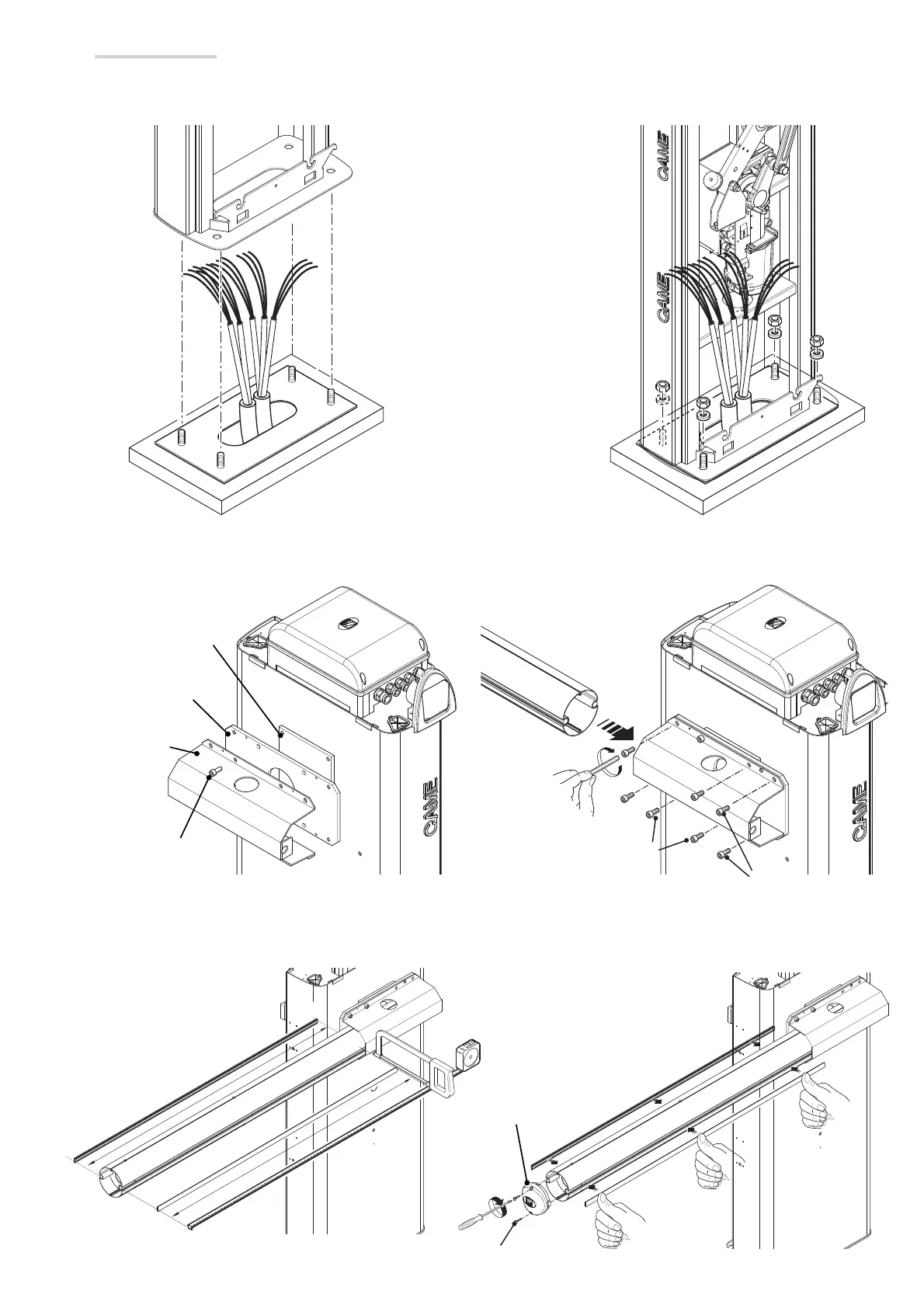
Cut the groove covers to the required length and insert them in the boom conduits on both sides.
Fit the boom cap using the screws.
Motor shaft plate
Intermediate plate
Boom-attachment
cover
Boom cap
Installing the barrier
The cabinet should be installed with the inspection hatch on the most accessible side to facilitate any work or adjustments.
Place the cabinet onto the anchoring plate and fasten it using nuts and washers.
Assemble the boom-attachment cover, intermediate plate and the motor shaft plate with a screw. Leave the screw loose to make it easier to
insert the boom.
Fit the boom into the attachment cover and fasten it using the screws.
 Loading...


