UNI 5931 M8x12
p.
11 - Manual Code:
119GV18ver.
1.1 12/2011 © CAME Cancelli Automatici S.p.a. - The data and information in this manual may be changed at any time and without obligation on the part of Came Cancelli Automatici S.p.a. to notify said changes.
ENGLISH
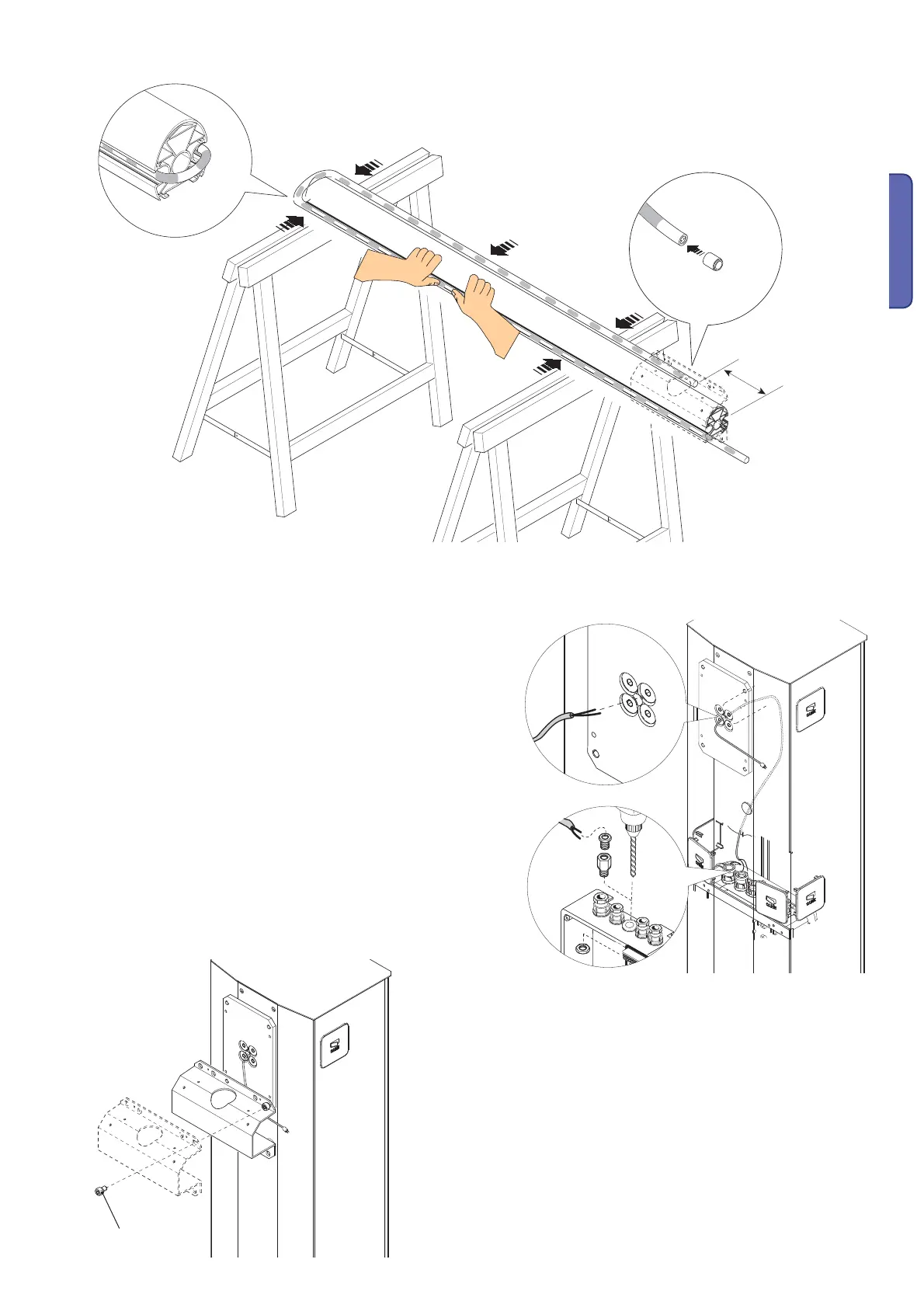
Insert the insulation cap into one of the two ends of the luminous cord.Insert by pressure the
luminous cord into the arm raceway, as shown in the fi gure..
Insert the power cable through the central hole in the transmission arm
plate.Perforate the control panel at one of the pre-perforated points
and fi t the cable gland;introduce and connect cables (see electrical
connections paragraph)
Position the arm-attachment cap against the transmission shaft plate with just
one screw and leave this loose.

 Loading...