28
48
①
②
③
④
⑨
⑦
⑤
⑥
⑧
⑥
p.
7 - Manual
FA00045-EN v.
2 - 09/2016- © Came S.p.A. - The contents of this manual may be changed, at any time, and without notice.
Preliminary checks
⚠
Before beginning, do the following:
• make sure you have set up a suitable dual pole cut off device along the power supply that is compliant
with the installation rules. It should completely cut off the power supply according to category III surcharge
conditions (that is, with minimum contact openings of 3 mm);
• setup suitable tubes and conduits for the electric cables to pass through, making sure they are protected
from any mechanical damage;
•
make sure that any connections inside the container (ones that ensure continuity to the protection
circuit) are fitted with additional insulation with respect to those of other electrical parts inside:
• make sure that the door is properly balanced; when stopped at any in-between point, it should hold its
position.
Cable types and minimum thicknesses
Connection Cable type
Cable length
1 < 15 m
Cable length
15 < 30 m
Control panel power supply 230 V AC H05VV-F
3G x 1.5 mm
2
3G x 2.5 mm
2
Flashing light
FROR CEI
20-22
CEI EN
50267-2-1
2 x 0.5 mm
2
Photocell transmitters 2 x 0.5 mm
2
Photocell receivers 4 x 0.5 mm
2
Command and safety device 2 x 0.5 mm
2
Antenna RG58 max 10 m
If cable lengths differ from those specified in the table, establish the cable sections depending on the actual
power draw of the connected devices and according to the provisions of regulation CEI EN 60204-1.
For multiple, sequential loads along the same line, the dimensions on the table need to be recalculated according
to the actual power draw and distances. For connecting products that are not contemplated in this manual, see
the literature accompanying said products.
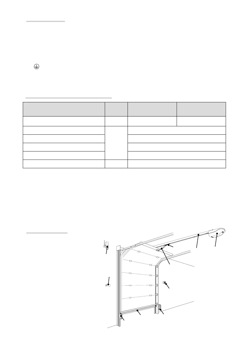
Standard installation
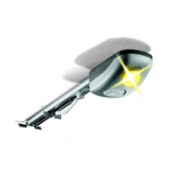
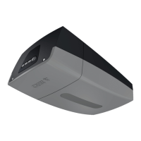
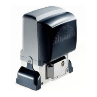
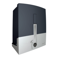
1. Operator
2. Traction guide
3. Release device
4. Transmission arm
5. Key-switch selector
6. Photocells
7. Control device
8. Sensitive safety-edge
9. Flashing light
 Loading...