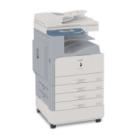
Chapter 1
21
F-1-48
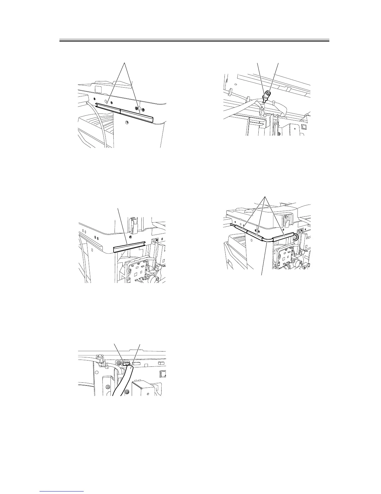
14) Affix the supplied harness cover (base) [1] at the
back of the machine with it aligned with the bottom
line of the reader.
F-1-49
15) Connect the connector of the repeating harness B
[1] to the connector J317 [2] on the image processor
PCB.
F-1-50
16) Using the supplied binding screw (M4x6) [1], se-
cure the repeating harness B clamp [2].
F-1-51
17) Using the three harness covers (lids) [2], secure
the repeating harness B [1] to the harness covers
(bases).
F-1-52
18) Using a nipper, remove the precut portion [1] of
the rear cover as shown below.
[1]
[1]
[2]
[1]
[1][2]
[1]
[2]