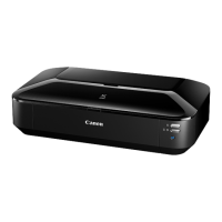
*1: To reassemble the unit after replacement, follow the procedures in the reverse order.
General notes:
- Make sure that the flexible cables and wires in the harness are in the proper position and connected
correctly. See 2-2. Disassembly & Reassembly Procedures or the Parts Catalog for details.
- Do not drop the ferrite core, which may cause damage.
- Protect electrical parts from damage due to static electricity.
- Before removing a unit, after removing the power cord, allow the machine to sit for approx. 1 minute
(for capacitor discharging to protect the logic board ass'y from damages).
- Do not touch the timing slit strip film and the timing slit disk feed film. No grease or abrasion is
allowed.
- Protect the units from soiled with ink.
- Protect the housing from scratches.
- Exercise caution with the screws, as follows:
i. The screws of the paper feed motor may be loosened only at replacement of the paper feed
motor unit (DO NOT loosen them in other cases).
ii. Before loosening the 3 screws that fix the carriage upper rail to the main chassis, or the 3
screws that fix the carriage rail to the main chassis, mark the screw positions so that the
carriage upper rail or carriage rail will be re-attached to the main chassis in their original
position. [See 2-2. Disassembly & Reassembly Procedures, (6) Carriage unit removal, for
details.]
upper rail details.]
In the service mode:
2. Print the integrated inspection pattern.
APP code
wheel gear
shaft
Paper guide
Timing slit
strip film
See 2-2. Disassembly & Reassembly Procedures, and
Parts Catalog.
Caution:
- Upon contact with the film, wipe the film with
ethanol.
- Confirm no grease is on the film. (Wipe off any
grease thoroughly with ethanol.)
- Do not bend the film.
In the user mode:
1. Perform print head alignment.
In the service mode:
2. Print the nozzle check pattern.
3. Perform LF / Eject correction (only
when uneven printing or streaks
appear on printouts after
replacement).
[See 3-3. Adjustment and Settings in
Service Mode, for details.]
Timing slit
disk feed
film
Print head In the user mode:
1. Perform print head alignment.
In the service mode:
2. Print the integrated inspection pattern.
<2-1. Major Replacement Parts and Adjustment>
 Loading...