1
- FRONT PANEL OF MACROPLUS -
Horizontal model
(LCD 4x20, characters 5mm, code MACRONEW01)
(LCD 4X20, characters 8mm, code MACRONEW00)
OUTPUT 1
OUTPUT 2
OUTPUT 3
OUTPUT 4
OUTPUT 5
OUTPUT 6
OUTPUT 7
OUTPUT 8
OUTPUT 9
OUTPUT 10
OUTPUT 11
OUTPUT 12
OUTPUT 13
OUTPUT 14
OUTPUT 15
OUTPUT 16
Vertical model
POWER ON
OUTPUT 1
OUTPUT 2
OUTPUT 3
OUTPUT 4
OUTPUT 5
OUTPUT 6
OUTPUT 7
OUTPUT 8
OUTPUT 9
OUTPUT 10
OUTPUT 12
OUTPUT 13
OUTPUT 14
OUTPUT 15
OUTPUT 16
ALARM
OUTPUT 11
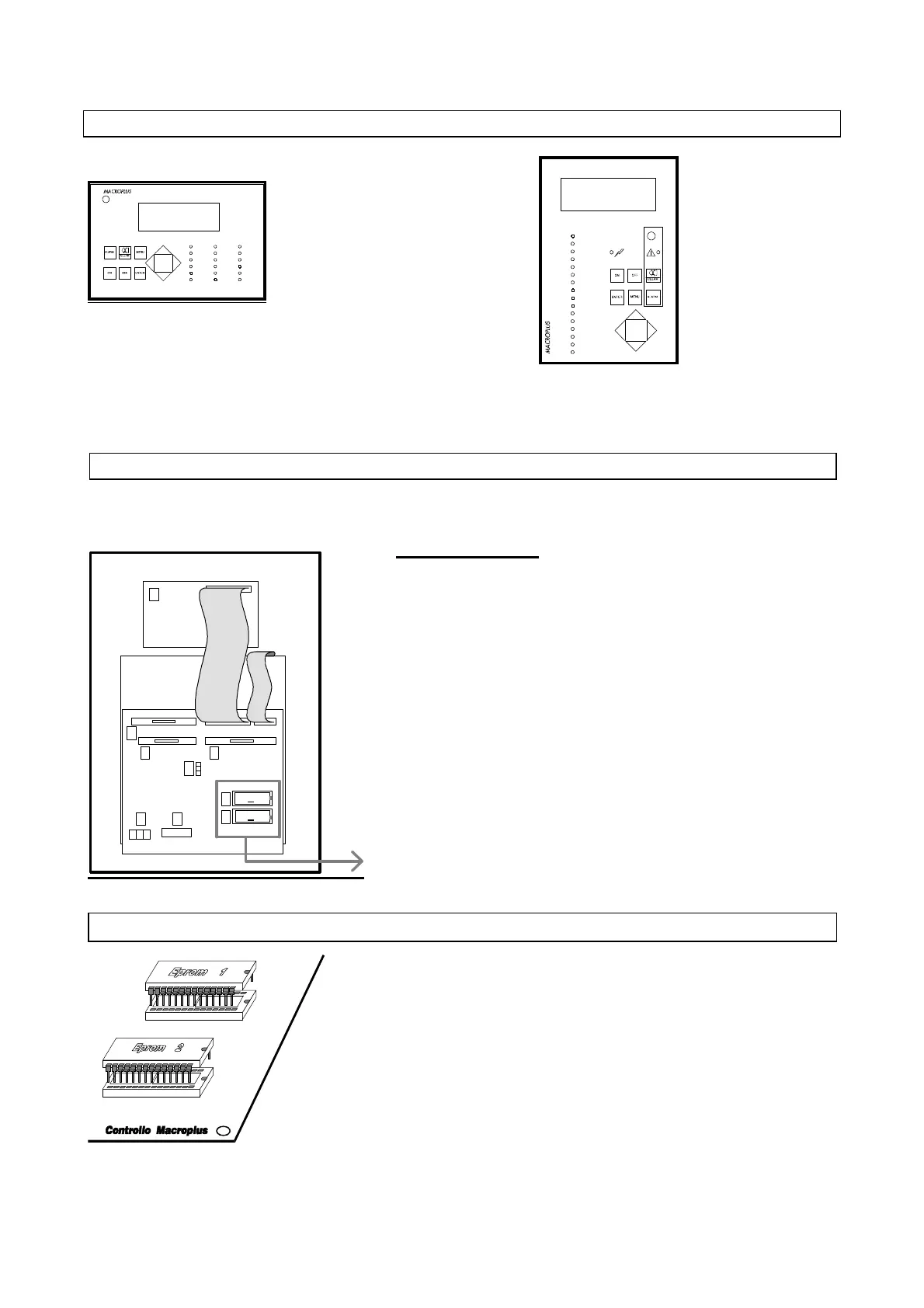
IMPORTANT
In order to ensure the correct functioning of the system, the two EPROMs
must be correctly inserted into their sockets. The notch on the surface of the
EPROM must align with the notch of the socket. To make this operation
simpler, make sure that the enamelled side of the EPROM coincides with
the enamelled side of the socket.
(LCD 4X20, characters 5mm, code MACRONEWV1)
(LCD 4X20, characters 8mm, code MACRONEWV0)
- REAR PART OF MACROPLUS (WITHOUT COVER) - CONTROL BOARDS -
Components
1. Clock board (code MNEWCLOCK0)
2. Output for serial interface (code MNEWRS4220) or for MODEM
(code MNEWRS232C)
3. Pin strip for selection of board RS232 (code MNEWRS2320)
4. (Optional) interface for RS232 printer (code MNEWRS2320) or for
ALFAPANEL printer (code MNEWALFA00)
5. First Eprom (BIOS)
6. Second Eprom (program)
7. Flat cable MACROPLUS-INTERFACE LARGE/SMALL
8. Terminal block
9. LCD
"SEE FIGURE BELOW"
- EPROMS -
3
4
7
5
6
8
2
1
9
1
2