6
- SELECTION 1ST/2ND BOARD -
DESCRIPTION
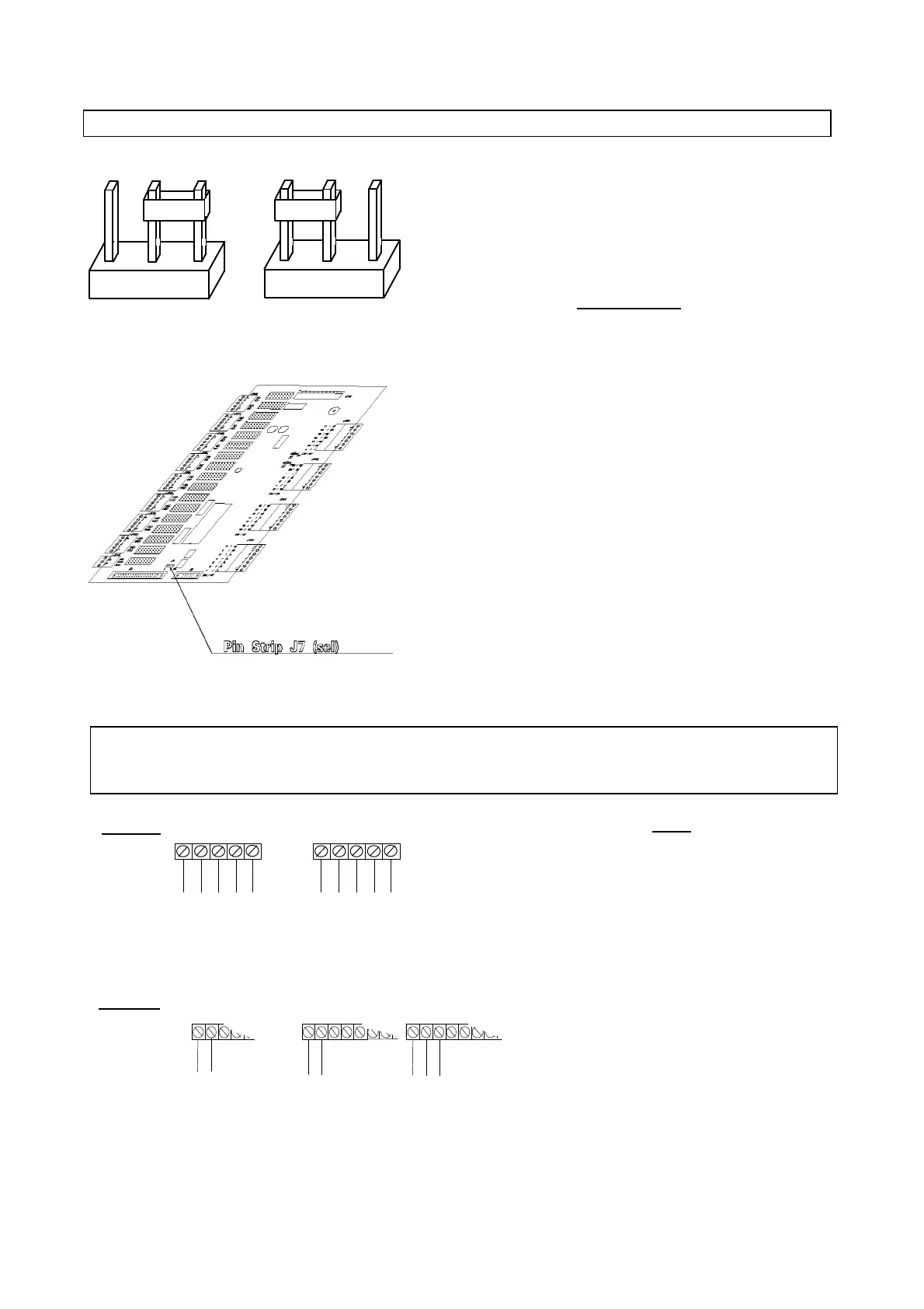
The pin-strip (j7) is a three-terminal selector placed on the
expandable boards (LARGE, SMALL EXPANDABLE and
SMALL NON-EXPANDABLE).
The figure on the right shows the two selections possible on the
pin-strip.
If your system requires two boards then it is necessary to
distinguish between them. Therefore select '0' (by means of the
pin-strip) on the first board, and '1' on the second board.
If you need just one board, set the link to '0'.
DEFAULT: POSITION "0"
Ano Anc
- TEMPERATURE PROBES CONNECTION
DIGITAL INPUTS (VOLTAGE-FREE CONTACTS)
KEYS
PROBES:
– + : Power supply -12/+12V (Max.
80mA available to power all the
connected probes)
M: Probe reference
Bn: Probe signal (-1 + 1 V)
DIGITAL INPUT:
C: Common
1,2..: Voltage-free contacts
ANALOGUE OUTPUT:
Y3: Analogue signal (0-10V, 10mA
max.)
G0: Reference
DIGITAL OUTPUT:
nC;nO: relay
ALARM RELAY:
Ac;Ano;Anc: (COMMON-NO-NC)
Alarm contacts
- M B4 B3 + C 4 3 2 1
Outputs Analogue Digital Alarm
Inputs Analogue Digital
1 0 1 0
POSITION 0 POSITION 1