4
Description of the system
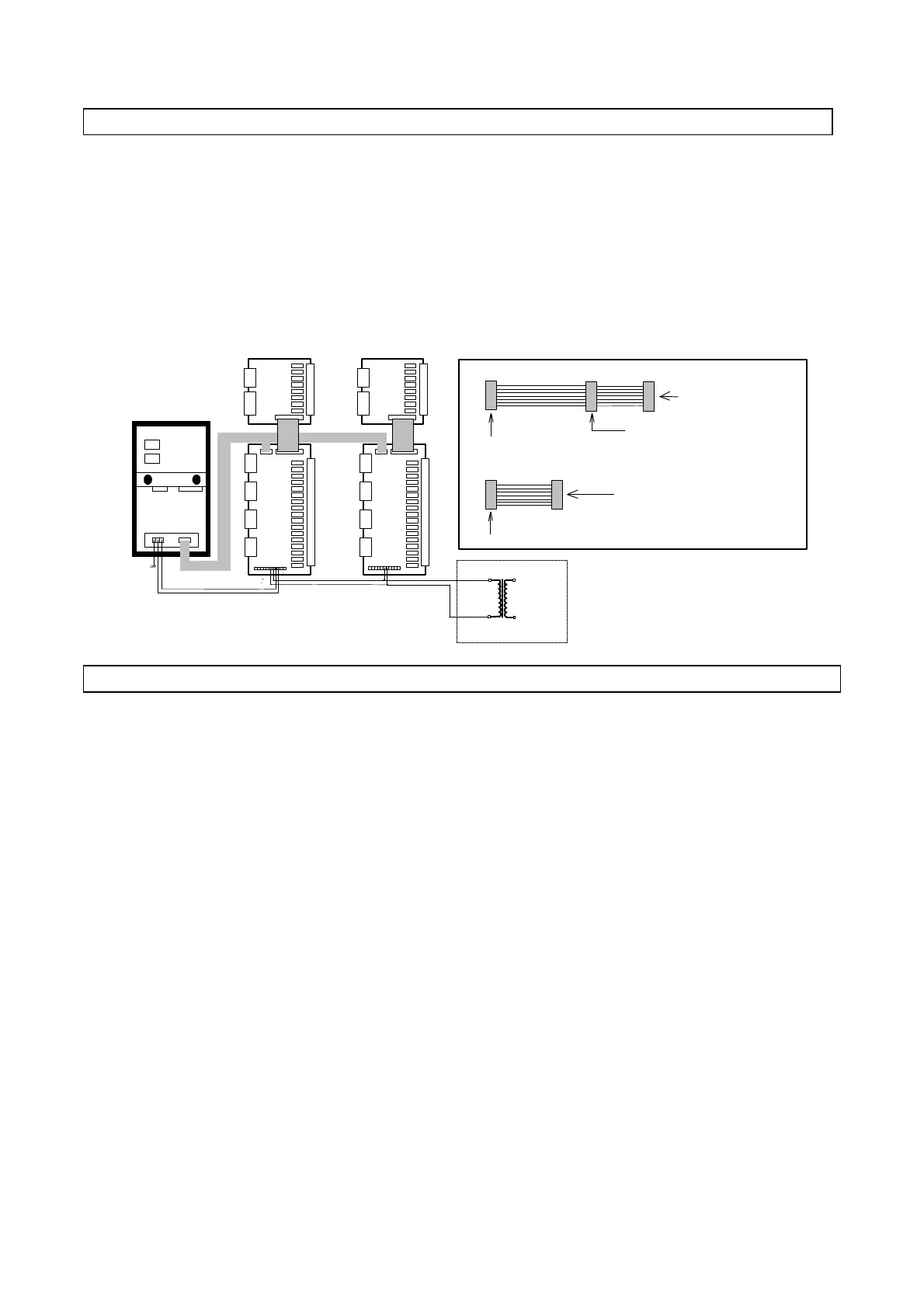
The maximum expansion of the system includes one MACROPLUS controller connected to two LARGE expansion
boards and two ADDITIONAL boards (available with screw or plug-in terminals).
All boards are powered with 24 V a.c.
To power the entire system use a transformer 220Va.c./24 Va.c. 100 VA .
Data transmission between the LARGE boards and Macroplus is carried out by means of a flat cable (code
59C222A003 / code 59C155A001) as indicated in the figure below.
The ADDITIONAL boards are connected to the LARGE boards (or SMALL EXPANDABLE) by means of a flat cable
soldered to the board and DO NOT REQUIRE POWER.
24 V a.c. 220 V a.c.
Supplied flat cable (code 59C155A001)
1,5 m
0,5 m
To the MACROPLUS board
To the first interface board
Supplied flat cable (code 59C222A003)
1 m
To the MACROPLUS board
To the interface board
To the second interface board
- ADVICE FOR OPTIMUM PERFORMANCE -
Avoid installing the Macroplus in places presenting the following characteristics:
1) Ambient temperature higher than 55 ° C or lower than -10 ° C;
2) Extreme changes of ambient temperature;
3) Relative humidity higher than 85%;
4) Presence of strong vibrations;
5) Exposure to jets of water;
6) Exposure to dust (dust can produce a corrosive covering causing possible oxidization, consequently
reducing insulation);
7) Exposure to aggressive and polluting agents (sulphuric and ammoniacal gases, salty agents, fumes) and
consequent corrosion and/or oxidization;
8) Strong magnetic interferences and/or high frequency (eg. near transmitting antennas);
9) Direct exposure to the sun or atmospheric agents in general.
ATTENTION
Before carrying out any electrical connection read carefully the
following instructions and see the diagrams on the next page.
Make sure that power supply is correctly wired so as to avoid any serious problem to the system.
1) Use cables suitable for terminals. Unscrew each screw, insert the cable, then fasten the screws. Pull lightly on the
conductors to make sure they are properly connected.
2) Keep the probe cables and the cables of the digital inputs separate from power cables to avoid any possible electromagnetic
noise. DO NOT place the power and probe cables in the same trunking (including those of the control panels).
- MAXIMUM EXPANSION LAYOUT (ELECRICAL CONNECTIONS) -