5
- The probe cables must not be near power devices (eg. contactors, overload switches, etc.);
- sensor cables should be as short as possible;
- Use shielded cables to connect the probes (min. cable section = 0.5 mm²).
3) Do not touch the electronic components mounted on the boards, this is to avoid any electrostatic discharges from the operator
to the components (that might consequently get damaged).
Handle the boards by the edges only.
4) Protection to earth
If the secondary of the power supply transformer is earthed, make sure that the earth cable has the same characteristics as the
cable linking controller and terminal G0.
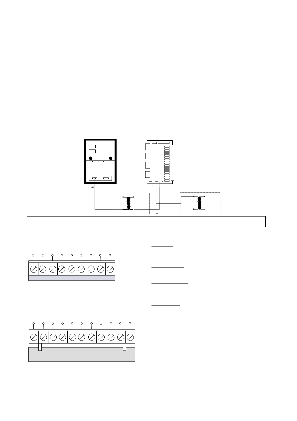
5) If the instrument is network-connected into a supervisory system via RS422, place a transformer 24V/24V between the
controller and the board to ensure the galvanic insulation of the controller. Use Carel transformer (24V, 24V, 20VA code
0907651AXX) that is supplied with the serial interface board (code MNEWRS4220).
The same precaution should be taken when using the serial board (code MNEWRS2320) when connecting Macroplus to a
computer. See diagram below.
6) The door of the panel where the controller is set must be connected to the panel by means of a braiding (min. section 12 mm
2
).
24 V a.c.
24 V a.c. 24 V a.c.
220 V a.c.
SMALL/LARGE (screw):
Electrical diagrams
- TERMINAL BLOCKS -
POWER POWER SENS. SENSOR
DERIV. SUPPLY COND.
LEVEL
OUT:+24V POWER POWER SENS. SENSOR
- + DERIV. SUPPLY COND. LEVEL
SMALL/LARGE (plug-in)
Electrical diagrams
- NOTES -
OUT+24V: Warning this OUTPUT: has been
designed for powering other appliances
(60 mA max) only.
POWER DERIV.: Is the 24Va.c. output that powers
MACROPLUS.
POWER SUPPLY: Connect the secondary of the 24Va.c.
transformer necessary to power the entire
system to these terminals.
SENS. COND.: Connect the conductivity sensor, if using the
LARGE board plus humidity option for the
control of the humidifier.
SENSORE LEVEL: Connect the water level sensor, if
using the LARGE board plus humidity
option for the control of the humidifier.
G0 G G0 24V~ CD2 CD1 L2 L1
G0 +24 G0 G G0 24V~ CD2 CD1 L2 L1