13
ENG
MPXPRO - + 0300055EN rel. 1.1 30/08/10
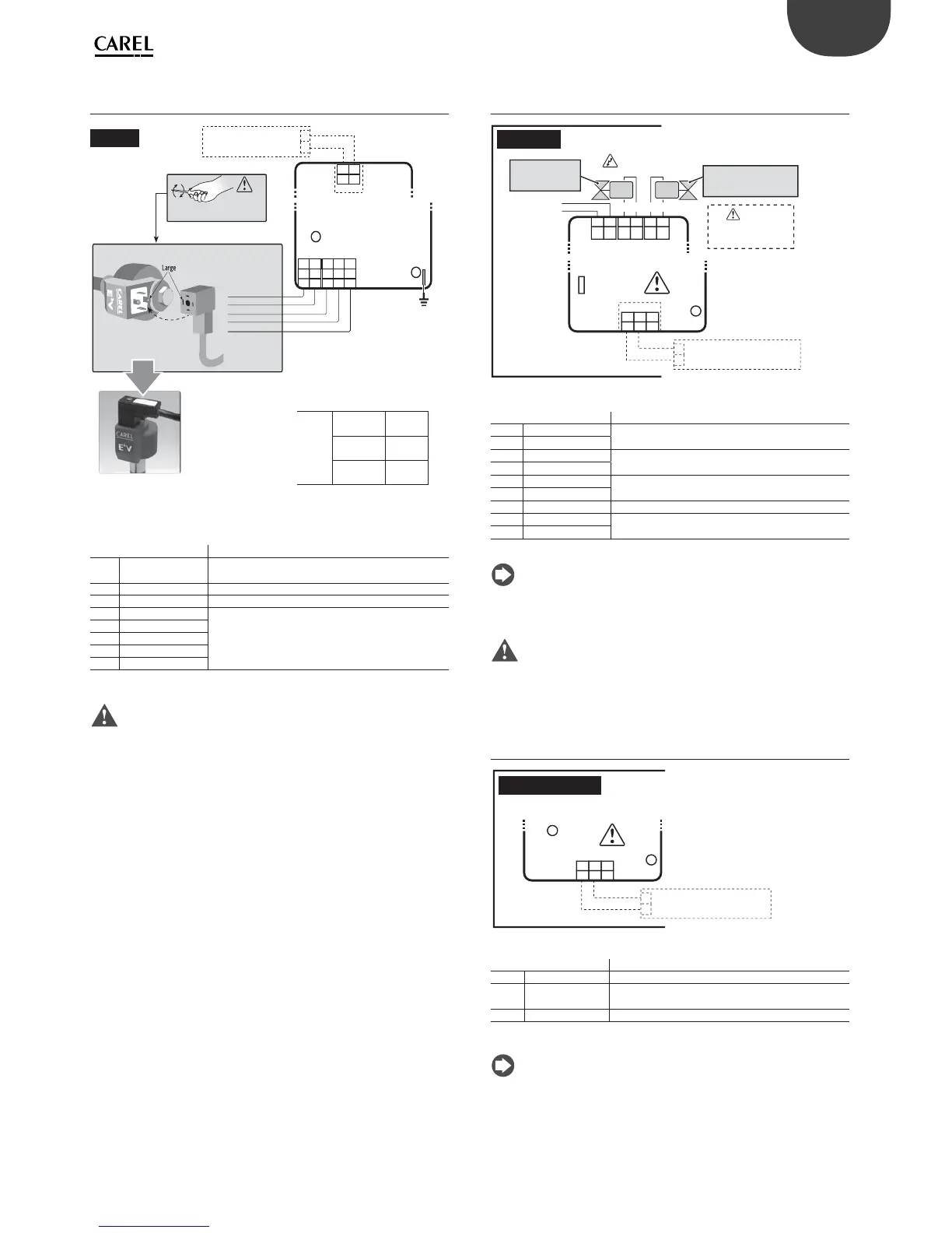
2.3 E
2
V driver expansion board
(MX3OPSTP**): terminals and connections
75
GND
CAREL E2VCABS*
E
2
V Driver
MX3OPST(H,U)*
73 74
8182 808384
13245
10
Vdc
GND
GR BR YE WH
Shield
L < 10m AWG22
L < 30m AWG20
L < 50m AWG18
Valve cable lenght without solenoid
do not connect to
any “GND” Terminal
Earth
0 to10 Vdc
Analogic
output only for
MX3OPST(H,U)0*
The input of the load 0 to 10 Vdc must
feature reinforced insulation with
reference to its internal power supply
Tight screw and nut after
installing connector/cable and E
2
V.
Unique correct
connection view
(no other possible
connections).
E2VCON* not suitable
for refrigeration
application.
Shield 80
White 81
Yellow/Black 82
Brown/Red 83
Green 84
E
2
V Driver
connection cable
CAREL E
2
V
For further information, please refere to the “EEV system guide”
(code +030220810) available in the web site www.carel.com, in the
literature section.
Cable Lenght
Valve cable lenght without solenoid
Fig. 2.g
Terminal Description
73
0 to 10 Vdc output,
4.5 mA MAX
Control signal for modulating actuators:
Maximum error 2% f.s., maximum load 2.2 KΩ
74 GND
75 Functional earth
80 Shield
Connection to CAREL
E
2
V valve with shielded cable
E2VCABS600
81 White
82 Yellow/black
83 Brown/red
84 Green
Tab. 2.a
Important:
• To connect the valve, use a CAREL shielded cable code E2VCABS*00
(AWG22) or an alternative suitably sized 4-wire shielded cable:
- reverse valve or valve size > = E3V45 -> solenoid required with
AWG22 shielded cable
- direct valve and valve size < E3V45 -> if the solenoid is installed
AWG22 shielded cable, if the solenoid is not installed, for the size of
the cables see the table to the side.
• the input of the 0 to 10 Vdc modulating actuator load must have
reinforced insulation, based on its internal power supply.
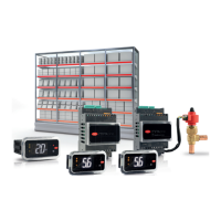
2.4 PWM driver expansion board
(MX3OPPWM**): terminals and connections
L
N
PWM
ac
PWM
dc
N L
+
–
GND
PWM Driver
MX2OPPWM*
64 6562 6360 61
6768 66
PWM
+
DC
-
PWM
N
AC
L
LN
10
Vdc
GND
0 to 10 Vdc
Fuse 0.25 AT
POWER SUPPLY
115-230 Vac
25 W max
Use
PWMac or PWMdc
valves alternatively
DC/AC output
Analogic
output only for
MX2OPPWM0*
The output 0 to 10 Vdc must feature
reinforced insulation with reference
to its internal power supply
PWM valve
115-230 Vac
20 W max 5 W min
PWM valve
115 Vdc RMS-230 Vdc RMS
20 W max 5 W min
Fig. 2.h
Terminal Description
60 L Power supply:
115 to 230 Vac, 50/60 Hz, 25 VA MAX
61 N
62 N Power supply PWM valve Vac:
115 to 230 Vac, 50/60 Hz, 5 W MIN, 20 W MAX
63 L
64 + Power supply PWM valve Vdc:
105 to 230 Vdc RMS, 5 W MIN, 20 W MAX
65 -
66 Not used
67 0 to 10 Vdc output Control signal for modulating actuators:
Maximum error 2% f.s., maximum load 2.2 KΩ.
68 GND
Tab. 2.b
Note:
• use either AC or DC PWM valves;
• the input of the 0 to 10 Vdc modulating actuator load must have
reinforced insulation, based on its internal power supply.
Important: do not use PWM valves with recti ed 230 Vac power
supply.
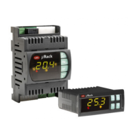
2.5 Expansion board 0 to 10 Vdc output
(MX3OPA1002): terminals and connections
GND
MX2OPA1002
4142 40
10
Vdc
GND
Analog
output
0 to 10 Vdc
The output 0 to 10 Vdc must feature
reinforced insulation with reference
to its internal power supply.
Analog 0 to 10 Vdc
Fig. 2.i
Terminal Description
40 Not used
41 0 to 10 Vdc output
Control signal for modulating actuators: Maximum
error 2% f.s., maximum load 2.2 KΩ.
42 GND
Tab. 2.c
Note: the input of the 0 to 10 Vdc modulating actuator load must
have reinforced insulation, based on its internal power supply.