7
ENG
MPXPRO - + 0300055EN rel. 1.1 30/08/10
1. INTRODUCTION
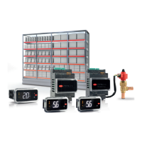
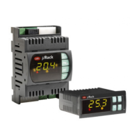
MPXPRO is an electronic controller for the for the complete and advanced
management of stand-alone or multiplexed showcases or cold rooms,
with or without built-in electronic expansion valve driver. It is designed for
DIN rail assembly and comes with plug-in screw terminals. The controller
can manage a local Master-Slave network with a at maximum of 6 units
(1 Master and 5 Slaves). Each controller can have its own display (read
only) and/or user terminal (display plus keypad for programming), or
alternatively the user terminal can be connected to the Master controller
which then displays the parameters for all controllers connected in the
network. The platform includes a wide range of models, di ering in
terms of type of controller (Master or Slave), the number of relay outputs
available (3 or 5 on the Slave controller), the type of probes that can be
connected (NTC only and 0 to 5 V ratiometric or NTC/PTC/PT1000/NTC
L243, 0 to 5 V ratiometric and active 4 to 20 mA, 0 to 10 V), the type of
built-in driver (for CAREL stepper or PWM electronic expansion valve),
whether or not there are two PWM outputs on the main board, and
whether or not there is a 0 to 10 Vdc output on the driver board. See the
table below.
Main features:
• compact structure, with built-in driver for CAREL stepper or PWM valve;
• Ultracap technology for emergency closing in the event of mains
power failure (no solenoid valve is required if the EEV valve is
installed in direct way and the size is smaller than E3V45)
• Built-in switching power supply for stepper valve option (external
transformer no longer required)
• Valve cable length extended to max 50m
• Display and master/slave network cable length extended to max 100m
• advanced superheat control with protection for low superheat
(LowSH), low evaporation temperature (LOP), high evaporation
temperature (MOP), low suction temperature (LSA);
• defrost activated from the keypad, digital input, network control from
Master, supervisor;
• management of various types of defrost, on one or two evaporators:
heater, natural (stop compressor), hot gas;
• smart defrost functions;
• coordinated network defrosts;
• light and showcase curtain management;
• anti-sweat heater modulation;
• evaporator fan speed modulation;
• remote control (accessory) for commissioning and programming;
• VPM program (Visual Parameter Manager), installed on a personal
computer, for managing parameters and testing the controller;
• possibility to display and set the Slave parameters from the Master;
• propagation of digital input from Master to Slave;
• display Slave alarms on the Master;
• sharing of one or more network probes (e.g. network pressure probe);
• management of network or local solenoid valve;
• remote management of Master light and AUX outputs on Slave;
• upload parameters from Master to Slaves;
• Master as gateway to supervisor for all Slaves;
• management of HACCP alarms.
Installation in direct way:
1.1 Models
The LIGHT version is supplied without the plastic side cover, it is not
possible to install the driver board for expansion valves and it is available
only in multiple packages without connector kit.
The following table shows the models and the main features, also see
paragraph 10.2:
Light Version
Model Code Features
Master/
Slave
rel. Type of relay RS485
& RTC
Board
Probe usable 2 PWM
output
E
2
V driver
& 0…10
Vdc output
PWM driver
& 0…10 Vdc
output
0…10 Vdc
output
NTC PTC,
Pt1000,
NTC L243
Ratiometric
probe
0…5 Vdc
Active probe
0…10 Vdc
4…20 mA
LIGHT
MX10M00EI11 Master 5 8A-2HP-16A-8A-8A Y(*) YES NO YES NO NO NO NO NO
MX10S00EI11 Slave 5 8A-2HP-16A-8A-8A I YES NO YES NO NO NO NO NO
MX10S10EI11 Slave 3 8A-0-16A-0-8A I YES NO YES NO NO NO NO NO
Tab. 1.a
Standard Version
Model Code Features
Master/
Slave
rel. Type of relay RS485
& RTC
Board
Probe usable 2 PWM
output
E
2
V driver
& 0…10
Vdc output
PWM driver
& 0…10 Vdc
output
0…10 Vdc
output
NTC PTC,
Pt1000,
NTC L243
Ratiometric
probe
0…5 Vdc
Active probe
0…10 Vdc
4…20 mA
FULL
MX30M21HO0 Master 5 8A-2HP-16A-8A-8A Y(*) YES YES YES YES Y I I I
MX30S21HO0 Slave 5 8A-2HP-16A-8A-8A I YES YES YES YES Y I I I
MX30S31HO0 Slave 3 8A-0-16A-0-8A I YES YES YES YES Y I I I
FULL + E
2
V
MX30M25HO0 Master 5 8A-2HP-16A-8A-8A Y(*) YES YES YES YES Y Y I NO
MX30S25HO0 Slave 5 8A-2HP-16A-8A-8A I YES YES YES YES Y Y I NO
FULL + PWM
MX30M24HO0 Master 5 8A-2HP-16A-8A-8A Y(*) YES YES YES YES Y I Y NO
MX30S24HO0 Slave 5 8A-2HP-16A-8A-8A I YES YES YES YES Y I Y NO
Tab. 1.b
(Y: tted, I: can be tted)
(*) The Master controllers have the clock (RTC) and the RS485 interface already
tted, the Slave controllers can become Masters by tting the MX3OP48500 card
(accessory) and setting a parameter (In). A Master controller can become a Slave
controller by simply setting the parameter (In).
The code identi es the type of controller and outputs:
• the fth letter, M or S, represents a Master or Slave controller
respectively;
• the seventh letter:
– 0= main board, driver board not pre-installed, NTC and 0 to 5 Vdc
ratiometric probe only;
– 1= full optional board with 2 PWM outputs, 12 Vdc (max 20 mA),
driver board not pre-installed, possibility to connect, as desired, NTC,
PTC, PT1000, NTC L243 probes, 0 to 5 Vdc ratiometric probes, 0 to 10
Vdc or 4 to 20 mA active probes
– 4= full optional board with 2 PWM outputs, 12 Vdc (max 20 mA),
PWM driver board pre-installed and including the 0 to 10 Vdc
output, all types of probes can be connected;
– 5= full optional board with 2 PWM outputs, 12 Vdc (max 20 mA), E
2
V
driver board pre-installed and including the 0 to 10 Vdc output, all
types of probes can be connected.
refrigerant outlet
refrigerant inlet