49
ENG
MPXPRO - + 0300055EN rel. 1.1 30/08/10
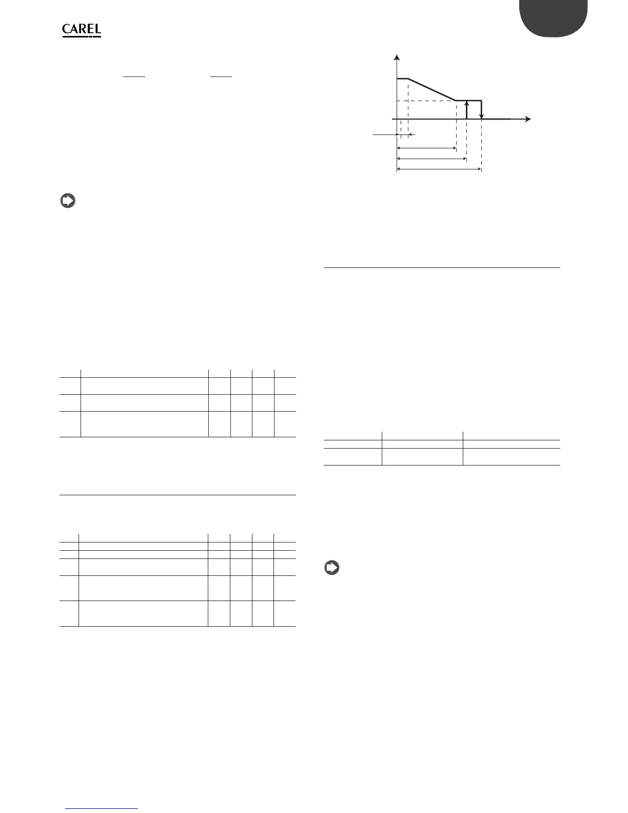
Thresholds dn1 (evaporator 1) and dn2 (evaporator 2) are de ned by:
dn1 = tE11, dn2 = tE12
dn
100
dn
100
The algorithm keeps a counter of the defrosts to be skipped:
• if the defrost ends in a time less than dn1, the counter of the defrosts
to be skipped is increased by 1;
• if the defrost ends normally, the next defrost is performed;
• when the counter reaches , 3, three defrosts are skipped and then the
counter is reset to 1;
• on power-up, the defrost is performed 7 times without increasing the
counter, from the eighth on the counter is updated.
Note: in power defrost mode (see the following paragraphs), the
maximum defrost duration dP1 and dP2 is increased by the value
of parameter ddP.
Power defrost (parameters ddt, ddP)
Power defrost is used to increase the end defrost threshold dt1 (dt2
for the second evaporator) and/or the maximum defrost duration dP1
(dP2 for the second evaporator). These increases allow longer and more
e ective defrosts. Power defrost are performed on each defrost call
during night status or when suitably con gured by the RTC parameters
(sub-parameter P of parameters td1 to td8), so as to allow the user to
choose the conditions that are most suitable for this special procedure.
Power Defrost is activated when at least one of the increases, ddt or ddP,
has any value other than zero.
Par. Description Def Min Max UoM
ddt Additional end defrost temperature delta
for Power defrost mode
0.0 -20.0 20.0 °C/°F
ddP Additional maximum defrost time delta for
Power defrost mode
0 0 60 min
P__ Defrost 1 to 8 – enable
Power defrost
0 = normal; 1= Power defrost
001-
Tab. 6.g.m
6.8 Evaporator fans
See paragraph 5.7. The advanced parameters for the evaporator fans
concern the minimum and speed maximum, the selection of the type
of motor (inductive or capacitive) and the setting of the start-up time.
Par. Description Def Min Max UoM
F6 Maximum fan speed 100 F7 100 %
F7 Minimum fan speed 0 0 F6 %
F8 Fan peak time
0 = function disabled
0 0 240 s
F9 Select fan control with output PWM1/2
(with phase cutting speed control)
0 = by pulse; 1 = by duration
101-
F10 Evaporator fan forcing time at maximum
speed
0 = function disabled
0 0 240 s
Tab. 6.h.a
F6: is the maximum fan speed, expressed as a % of the output. For 0 to
10 V outputs, it represents the output voltage at maximum speed as
a percentage. For phase control outputs, it represents the maximum
portion of the semi-wave applied to the load as a percentage. The same
is true for the minimum speed set for F7. The fan peak time F8 represents
the operating time at maximum speed set using parameter F6 to
overcome the mechanical inertia of the motor. F10 represents the time
the fan is operated at maximum speed for the peak time (F8).
If the evaporator fan speed is controlled with phase control, F9 determines
the type of control:
F9=0: by pulse, for capacitive motors;
F9=1: by duration, for inductive motors.
See paragraph 5.7 for the meaning of parameters F5, F1, Frd.
F5+1
F5
F1
t
FAN
SPEED
0%
F7
F6
F1-Frd
Fig. 6.m
6.9 Electronic valve
The stepper electronic valve requires a power supply to be able to open
or close.
Starting from version 2.8, MPXPRO features a special ultracap to guarantee
the power required to close the electronic valve in the event of power
failures. Further details on installing and selecting the cable are shown in
the section on connections and wiring diagrams.
The ultracap takes around 2 minutes to charge completely when
completely discharged. It is therefore recommended to set a delay time
no less than 2 minutes for compressor and evaporator fans enabling in
power-up (parameter c0).
Introduction
MPXPRO, depending on the optional cards installed, can manage
di erent types of electronic expansion valve. Speci cally:
Driver Code Model of valve
stepper MX3OPSTP* CAREL E
2
V
PWM MX3OPPWM**
PWM 115 to 230 Vac
PWM 110 to 230 Vdc
Tab. 6.i.a
To manage the electronic expansion valve, two additional probes must
be installed and suitably con gured:
• temperature probe for measuring the superheated gas temperature at
the evaporator outlet.
• pressure probe for the measurement of the saturated evaporation
pressure / temperature at the evaporator outlet.
Installation notes:
MPXPRO is designed to manage one electronic expansion valve that
controls the ow of refrigerant inside an individual evaporator. Two
evaporators in parallel cannot be managed with just one electronic
expansion valve.
• The NTC/PTC/PT1000/NTCL243 temperature probe must be installed
near the evaporator outlet, according to the standard installation
methods (see the installation notes on the E
2
V instruction sheet).
Suitable thermal insulation is recommended. CAREL o ers special
types of probes designed to simplify installation in contact with the
refrigerant pipe:
– NTC030HF01 for Retail use IP67, 3m, -50T90 °C, 10 pcs
– NTC060HF01 for Retail use IP67, 6m, -50T90 °C, 10 pcs
To measure the saturated evaporation temperature, di erent types
of probes can be used; in particular, the following can be con gured
(advanced parameter /FE):
• 0 to 5 V ratiometric pressure probe (recommended by CAREL);
• NTC/PTC/PT1000 temperature probe;
• 4 to 20 mA active pressure probes (powered externally).
t= temperature