34
ENG
MPXPRO - + 0300055EN rel. 1.0 30/08/10
Auxiliary / light serving the Master on the Slaves (H1, H5, H7 = 4/6)
From the Master, the action of the auxiliary output is propagated via tLAN
to the Slaves whose digital output is con gured as H1=4, for the auxiliary
output, and H1=6 for the light output.
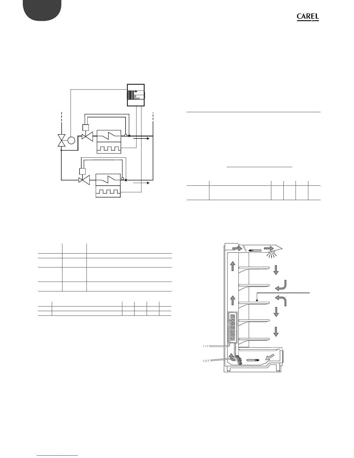
Auxiliary evaporator defrost (not compatible with electronic
expansion valve management)
A heater can be activated to perform a heater defrost on the main and
auxiliary evaporator.
M
MPXPRO
CAREL
!
MASTER
SV
MPXPRO
E
E
T
T
V
V
Fig. 5.d
Key
E Evaporator with electric defrost SV Solenoid valve
V Thermostatic expansion valve
MPXPRO can manage defrosts with one or two outputs and one or two
end defrost probes. The table below summarises the possible cases:
Defrost
outputs
Evaporator
probes
Control
1 1 normal
21
defrost managed on two outputs with reference to
the same evaporator probe
12
defrost managed on the same output with
reference to two evaporator probes (minimum
evaporation temperature)
22
defrost managed independently on the two
evaporator circuits
Tab. 5.k
Par. Description Def Min Max UoM
Sd1 Defrost probe - - - °C/°F
Sd2 Secondary evaporator defrost probe - - - °C/°F
Tab. 5.l
Evaporator fans
This con guration involves using the auxiliary output for the evaporator
fans; the activation/deactivation of the evaporator fans is signalled by the
evaporator fan icon on the display. See paragraphs 5.7 and 6.8.
Anti-sweat heaters
This con guration involves using the auxiliary output to demist the
display cases (control with xed activation, see paragraph 6.3).
Suction and equalizing valve
This con guration involves using the auxiliary output as a suction or
balancing valve for hot gas defrosts. See paragraph 5.6.
Liquid solenoid valve
Available only for R1 AUX4 (modi able only with H13), used to activate
the liquid solenoid valve when ultracap technology is not available or in
applications with thermostatic valves.
NB: the solenoid function in the instrument is always active, even if the
corresponding output is not con gured. The icons and variables on the
supervisor will thus re ect normal operation of the instrument
5.5 Control
Introduction
There are various modes for controlling air temperature for the
conservation of foodstu s in cold rooms and showcases. The following
gure shows the position of the intake probe Sr and the outlet probe
Sm. The virtual probe Sv is a weighted average of these two, based on
parameter /4, according to the following formula:
Sv =
Sm toSr t
Par. Description Def Min Max UoM
/4 Virtual probe composition
0 = outlet probe Sm
100 = intake probe Sr
0 0 100 %
Tab. 5.m
For example if /4=50, Sv=(Sm+Sr)/2 represents the estimated value of the
air temperature around the food being cooled.
Example: vertical showcase
DAY
Sm
Sv=(Sm+Sr)/2
Sr
Fig. 5.e
Key
Sm Outlet probe Sv Virtual probe
Sr Intake probe