26
ENG
MPXPRO - + 0300055EN rel. 1.0 30/08/10
4. COMMISSIONING
4.1 Con guration
Once the electrical connections have been completed (see the chapter
on Installation) and the power supply has been connected, the operations
required for commissioning the controller depend on the type of
interface used, however essentially involve setting the so-called initial
con guration parameters. See the guided commissioning procedure.
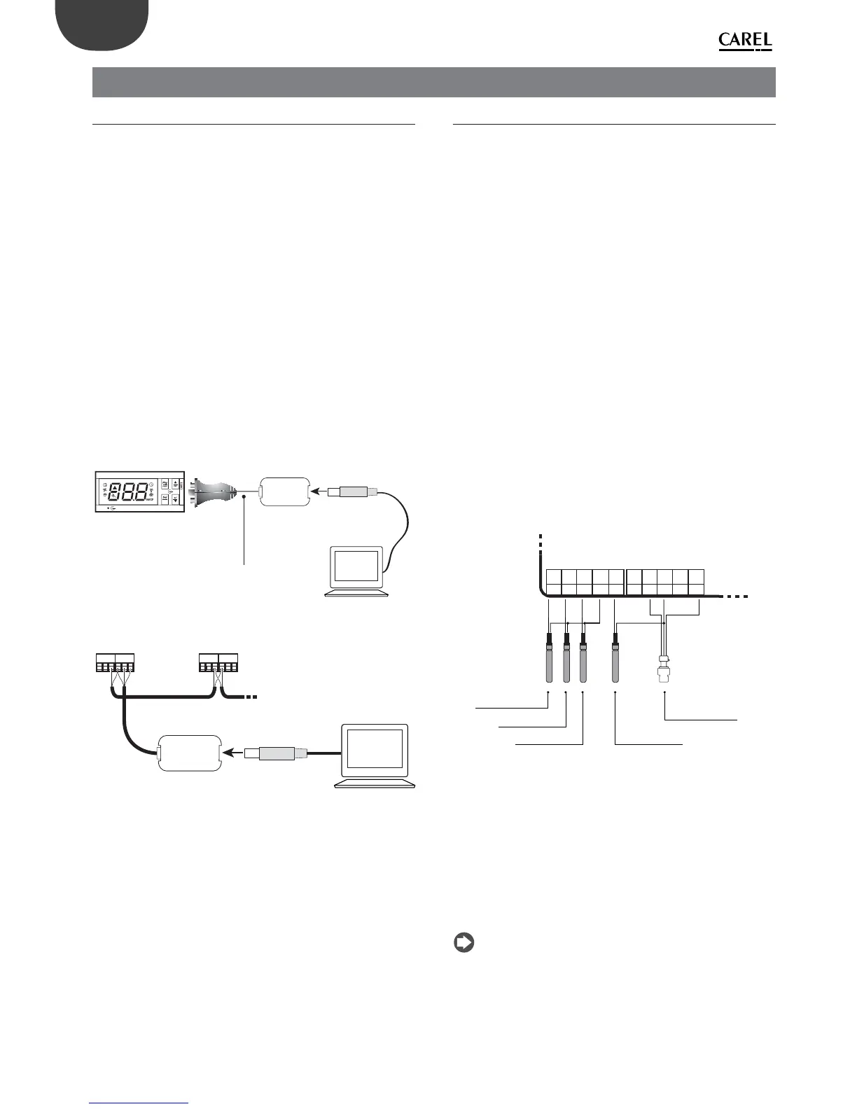
1. MXOPZKEYYA0 / IROPZKEYA0 ( rmware 1.x) programming key.
MPXPRO can be con gured using programming keys that have
themselves been programmed. In this case, simply plug the key into
the connector. The operation must be performed with the controller
o . After loading the parameters the controller can be started.
2. Commissioning tool software, VPM. This procedure is used to
program and test the operation of the MPXPRO from a PC during
commissioning when starting the system. In particular, this method
is used to:
• set the values, visibility and attributes of all the parameters
(including unit parameter);
• completely program a key;
• during start-up, monitor and manually override all the inputs/
outputs;
• update the rmware.
The commissioning tool can be connected from the PC via:
a: a dedicated port available on some user terminals/remote
displays
USB
tLAN
commissioning
cable
Terminal
IR00UGC300
IR00XGC300
IROPZTNL00
USB/tLAN converter
PC
AUX
MPXPRO
Fig. 4.a
b: the RS485 supervisor network
MASTER SLAVE
USB
RS485
tLAN
CVSTDUMOR0
USB/RS485 converter
PC
Fig. 4.b
3. User terminal. When rst started, MPXPRO activates a special
procedure to set the critical parameters for:
• correct communication of the controller with a supervisor and Master/
Slave network;
• management of the electronic valve.
This procedure can be disabled from the key or commissioning tool
(VPM). During this procedure, the device remains in standby and the
functions are disabled (including control and communication via
RS485 or tLAN). The special con guration menu is only displayed on
the user terminal, consequently one needs to be connected if the
function is not disabled (avoiding con icts in the network/LAN or
return of liquid refrigerant to the compressor).
Only after having set all the required parameters can normal
con guration be performed.
4. Remote control. When rst started, this can be used to directly
con gure the critical parameters without needing to activate the
synchronization function (synch button).
4.2 Recommended initial con guration
MPXPRO features highly con gurable inputs and outputs. CAREL in any
case recommends the basic con guration following the default settings
of the parameters. By following this suggestion, the controller can
independently manage the main functions in most applications, without
having to signi cantly modify the settings of the parameters.
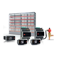
Inputs
The default con guration involves:
Group 1: NTC temperature probes on the showcase:
• S1: NTC outlet probe Sm;
• S2: NTC defrost probe Sd;
• S3: NTC intake probe Sr.
Group 2: superheat control:
• S4/DI1: NTC superheated gas temperature probe on evaporator outlet
(con gured only on models with valve driver included, see parameter
/Fd)
• S5/DI2: input not active;
Group 3: superheat control:
• S6/DI3: ratiometric evaporator pressure probe (con gured only on
models with valve driver included, see advanced parameters /P3, /U6,
/L6, /FE).
Group 4:
• S7: input not active.
Group 5:
• digital input DI5 not active (see parameter A12)
5Vdc
S7/
DI4
GND
S6/
DI3
S5/
DI2
36
S2S1 S3
3537 33
S4/
DI1
GND
3234 30 2931 28
NTC NTC NTC NTC
air o temperature
probe (Sm)
defrost temperature
probe (Sd)
air on temperaure
probe (Sr)
superheated
gas probe (tGS)
saturated evaporation
pressure/temperature
proibe (PEu/tEu)
NTC NTC NTC NTC RATIOMETRIC
Default connections:
Fig. 4.c
Outputs
The default con guration involves:
Relay 1: solenoid valve/compressor (not modi able);
Relay 2: light (see parameter H7);
Relay 3: defrost (not modi able);
Relay 4: evaporator fans (see parameter H1);
Relay 5: alarm (see parameter H5);
PWM 1: anti-sweat heater control, see paragraph 6.3.
PWM 2: evaporator fan speed control, see FAN category parameters.
Note: VPM (Visual Parameter Manager) can be used to modify the
relay mapping.