52
ENG
MPXPRO - + 0300055EN rel. 1.0 30/08/10
PID control (parameters P4,P5,P6)
The opening of the electronic valve is controlled based on the di erence
between the superheat set point and the actual superheat calculated by
the probes. The speed of variation, the reactivity and the ability to reach
the set point depend on three parameters:
Kp = proportional gain, parameter P4;
Ti = integration time, parameter P5;
Td = derivative time, parameter P6;
The ideal values to be set vary depending on the applications and the
utilities managed, nonetheless default values are proposed that allow
good control in the majority of cases. For further details, refer to classic
PID control theory.
Par. Description Def Min Max UoM
P4 Proportional gain 15.0 0.0 100.0 -
P5 Integration time
0 = function disabled
150 0 900 s
P6 Derivative time
0 = function disabled
5.0 0.0 100.0 s
Tab. 6.i.k
P4: this represents the ampli cation factor. It determines an action that
is directly proportional to the di erence between the set point and the
actual superheat value. It acts on the speed of the valve, in terms of
steps/°C. The valve moves P4 steps for every degree centigrade variation
in the superheat, opening or closing whenever the superheat increases
or decreases respectively. It also acts on the other control factors, and is
valid in both normal control and with all emergency control functions.
High values ==> fast and reactive valve (e.g. 20 for CO
2
- carbon dioxide
applications).
Low values ==> slow and less reactive valve.
P5: this represents the time required by the controller to balance the
di erence between the set point and the actual superheat. It practically
limits the number of steps that the valve completes each second. It is
only valid during normal control, the special functions in fact have their
own integration time.
High values ==> slow and less reactive valve (e.g. 400 for CO
2
- carbon
dioxide applications)
Low values ==> fast and reactive valve
P5 = 0 ==> integral action disabled
P6: this represents the reaction of the valve to variations in the
superheat. It ampli es or reduces variations in the superheat value.
High values ==> fast variations
Low values ==> limited variations
P6 = 0 ==> di erential action disabled
Example. For CO
2
- carbon dioxide applications: P6=5
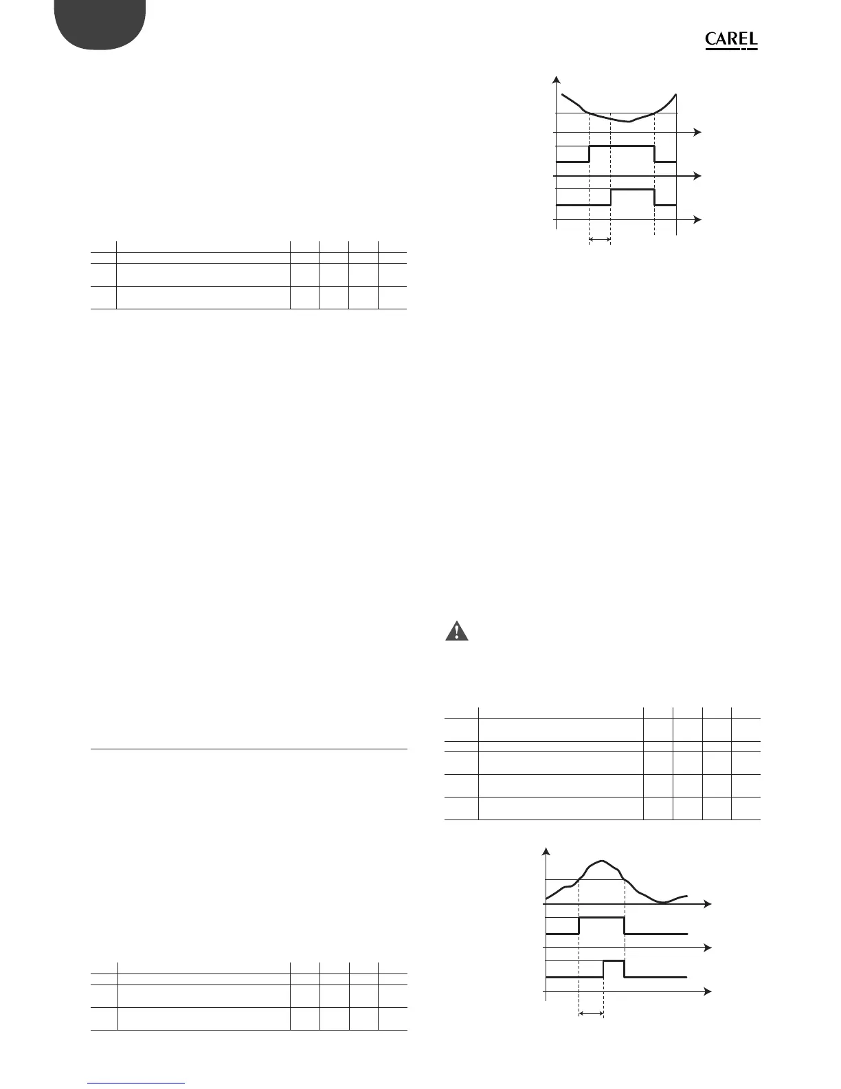
6.10 Protectors
LowSH Low superheat
To prevent too low superheat values that may cause the return of liquid to
the compressor or system instability (swings), a low superheat threshold
can be de ned, below which a special protection function is activated.
When the superheat falls below the threshold, the system immediately
enters low superheat status and activates a control action, in addition
to normal control, with the aim of closing the electronic valve more
quickly. In practice, the intensity of the system “reaction” is increased. If
the device remains in low superheat status for a certain period, a low
superheat alarm is activated, with the display showing the message ‘LSH’.
The low superheat signal features automatic reset, when the condition
is no longer present or the controller is switched o (standby). When
low superheat status is activated, the local solenoid valve can be forced
closed (parameter P10).
Par. Description Def Min Max UoM
P7 LowSH: low superheat threshold 7.0 -10.0 P3 K
P8 LowSH: integration time
0 = function disabled
15.0 0.0 240.0 s
P9 LowSH: alarm delay
0 = alarm disabled
600 0 999 s
Tab. 6.j.a
t
B
P9
t
t
ON
P7
LowSH
SH
OFF
ON
ALARM
OFF
Fig. 6.s
Key
SH Superheat P7 LowSH threshold
LowSH Low superheat protection P9 Alarm delay
ALARM Alarm t time
MOP Maximum evaporation pressure
When starting or restarting an installation, the compressors may
not be able to satisfy the simultaneous refrigeration requirements
of all the refrigeration utilities in the installation. This may cause an
excessive increase in the evaporation pressure and consequently the
corresponding saturated temperature. When the evaporation pressure,
expressed in degrees (saturated), rises above the threshold, after a certain
settable time the system enters MOP protection status: PID superheat
control is stopped and the controller starts gradually closing the valve
with an integration action to return the evaporation pressure below
the threshold. The protection function has been designed to allow a
gradual return to normal operating conditions, that is, when the critical
conditions have ended, the controller temporarily operates with a higher
superheat set point until the function is automatically reset.
Important: if this action causes the complete closing of the
electronic valve, the solenoid valve is also closed, even if this is a
network solenoid valve, when enabled. The alarm signal with the
message ‘MOP’ on the display is delayed from the activation of the
protection function and is automatically reset as soon as the saturated
temperature falls below the threshold.
Par. Description Def Min Max UoM
PM1 MOP: saturated evaporation temperature
threshold
50.0 -50.0 50.0 °C/°F
PM2 MOP: integration time 10.0 0.0 240.0 s
PM3 MOP: alarm delay
0 = function disabled
0 0 999 s
PM4 MOP function delay when starting
control
2 0 240 s
PM5 MOP: enable close solenoid valve
(optional)
001-
Tab. 6.j.b
t
PM3
t
t
ON
PM1
MOP
T_EVAP
OFF
ON
ALARM
OFF
Fig. 6.t