15
ENG
MPXPRO - + 0300055EN rel. 1.1 30/08/10
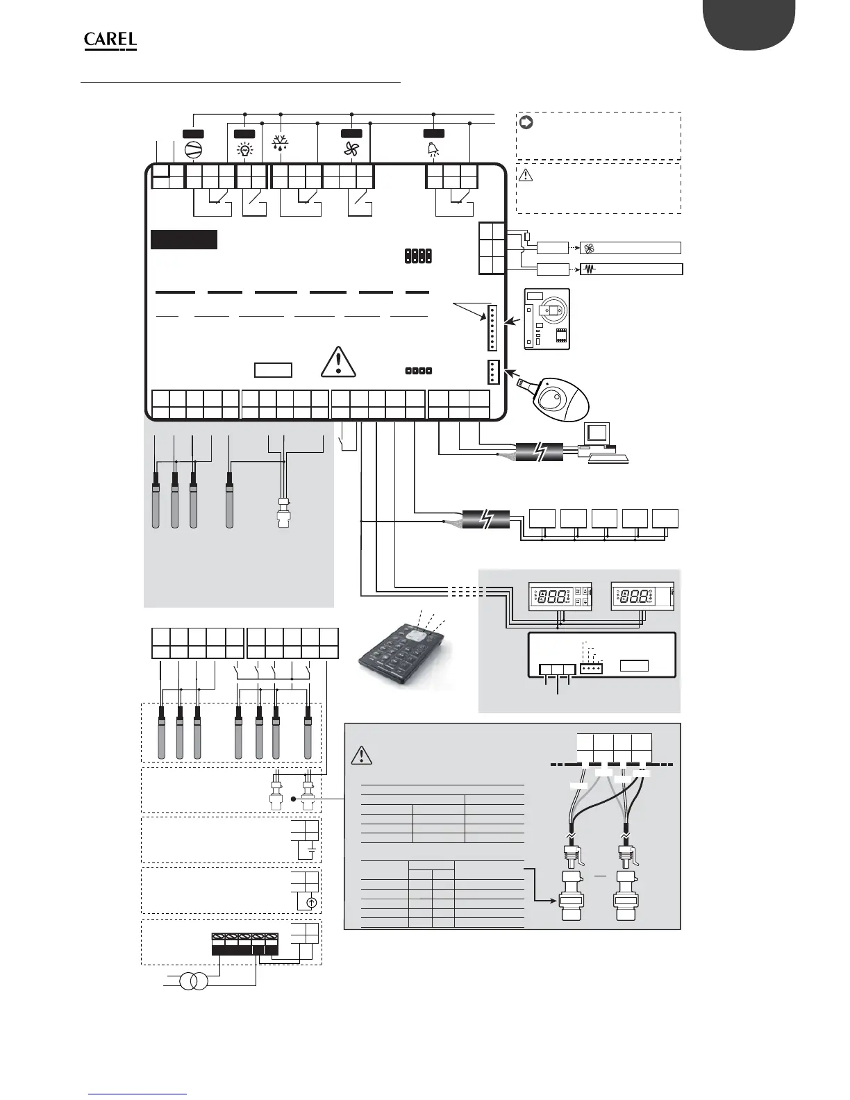
2.8 General connection diagram
5Vdc
S7/
DI4
GND VL
VL (25)
GND
GND (26)
DI5 GND
M.S.N.
Tx/Rx
T.U.I.
Tx/Rx
T.U.I.
Tx/Rx (24)
Tx/Rx+ Tx/Rx-
S6/
DI3
S5/
DI2
L
N
AC 115-230 V
200 mA max
LOAD 1
LOAD 2
AUX3
AUX1
AUX2
(
(
((
((
MX30P485**
6 (4) A N.O.
6 (4) A N.C.
6 (4) A N.O.
6 (4) A N.C.
EN60730-1
R1
R1
R5
10 (10) A N.O.
R2
R2
8 (2) A N.O.
8 (2) A N.C.
R3
R3
6 (4) A N.O.
R4
R4
R5
LN
8 9
NO NC C
10 11 12
NO C
13 14 15
NCNO C
16
36
S2S1 S3
35
1718
12 VPWM1PWM2
19
324
NO NC CNL
67
CNO
51
37
33
S4/
DI1
GND
3234 30 2931 25 24262728 2223 2021
-10T50
MX30**H**
AUX
AUX
IR *U* IR*X*
2930
S7/
DI4
GND
2930
S7/
DI4
GND
282930
31
5Vdc
S7/
DI4
GND
S6/
DI3
NTC NTC NTC NTC
1 2 3
0T50
Power
Supply
Rx/Tx
Gnd
36
S2S1 S3
3537 33
S4/
DI1
GND
34
5Vdc
S7/
DI4
GND
S6/
DI3
S5/
DI2
32 30 2931 28
Power Supply
Rx/Tx
GND
GND
SSR1
MCHRTF
R=
470 Ω
2930
S7/
DI4
GND
NTC
out
+G
NTC
out
M
-G0
out
H
AC 24 V
AC 230 V
50 Hz
AUX4
VL (25) GND (26)
T.U.I.
Tx/Rx (24)
Power Supply
AC 115-230 V
200 mA max
PWM modulating fans
20 mA max totally
Trim heater
Expansion board:
- 0 to10 Vdc Analog output MX3OPA10**
- PWM driver MX3OPPWM**
- E
2
V driver MX3OPSTP**
PROG. KEY
CLOCK
and
SERIAL INT.
Mounted on
MX30S*****
Maximum currents with removable vertical connectors cod. MX30***(C,I,O)**.
For more details, please refer to the technical leaets.
To be used only with
control switch o
(no Power Supply) and
disconnected from the RS485
supervisory serial line
MX3OP48500
(only for slave models MX30S*****)
Only “Master units”
to be connected
on RS485
Master/Slave network: max. cable lenght 100 m with a section not less then AWG20
Supervisor
RS485
Terminal/user interface: max. cable lenght 100 m with a section not less then AWG20
tLAN
Connection: (see the technical
leaets +050000135)
IR *U* IR*X*
Slave 1 Slave 2 Slave 4 Slave 5
Ratiometric
pressure
probe 0 to 5 Vdc
Analogic input
0 to 10 Vdc
(external power
supply)
0 to 10 Vdc
NTC /PTC/Pt1000
AIR OFF TEMPERATURE
PROBE (Sm)
DEFROST TEMPERATURE
PROBE (Sd)
AIR ON TEMPERATURE
PROBE (Sr)
SUPERHEATED GAS
PROBE (tGS)
SATURATED EVAPORATION
PRESSURE/TEMPERATURE
PROBE (PEu/tEu)
Analogic input
4 to 20 mA
(external power
supply)
4 to 20 mA
Slave 3
Pressure probe connection:
Black
White
Green
White
Use only one pressure probe
OR
probe ref. probe ref.
NTC NTC NTC NTC RATIOMETRIC
Shield
Shield
Default connection:
Possible connection:
The contemporary operation of both
outputs is not granted with any
actuator. Please refer to the technical
features.
Humidity probe
DPWC111000
remote infrared
IRTRMPX000
Warning: Before making any operation on
the control board, turn o the supply mains
turning o the main switch of the
electrical panel.
tLan
MXOPZKEYA0 (with rel. 2.x)
IROPZKEYA0 (with rel. 1.x)
Fig. 2.o
Important:
• the board must not be installed on surfaces that exceed 70
°C at 50 °C ambient and 80 °C with 60°C ambient;
• use an external disconnect switch positioned near the
appliance that is compliant with the IEC60947-1 and
IEC60947-3 standards;
• use cables rated to 90°C, if the temperature of the terminals
exceeds 85 °C, use cables rated to 105 °C;
• the connection cables must guarantee insulation up to 90
°C and if necessary up to 105 °C, when the temperature of
the terminals and relays exceeds 85 °C;
• if the appliance is used in a way that is not described by the
manufacturer, the speci ed level of protection may be a ected;
• if the current is higher than 6 amperes on R1, R2, R3, R4, R5, only
use cables with a cross-section of 2.5 mm
2
(14 AWG);
• the board must not be accessible to unauthorised personnel.
Connection with CAREL cable
SPKC002310 or SPKC005310
connection with
terminal colour
28 5 Vdc black
29 S7/D14 white
30 GND green
31 S6/D13 white
CAREL electronic pressure probe
CAREL code
range (barg)
ref. probe
min max
SPKT0053R0 -1.0 4.2 2CP5-52
SPKT0013R0 -1.0 9.3 2CP5-46
SPKT0043R0 0.0 17.3 52CP36-01 / 2CP5-66
SPKT0033R0 0.0 34.5 2CP5-47
SPKT00B6R0 0.0 45.0 2CP50-1