Modular Standard HP Chiller for Carel driver
Carel code +030221236- Rel. 1.0 dated 7 July 2003
15
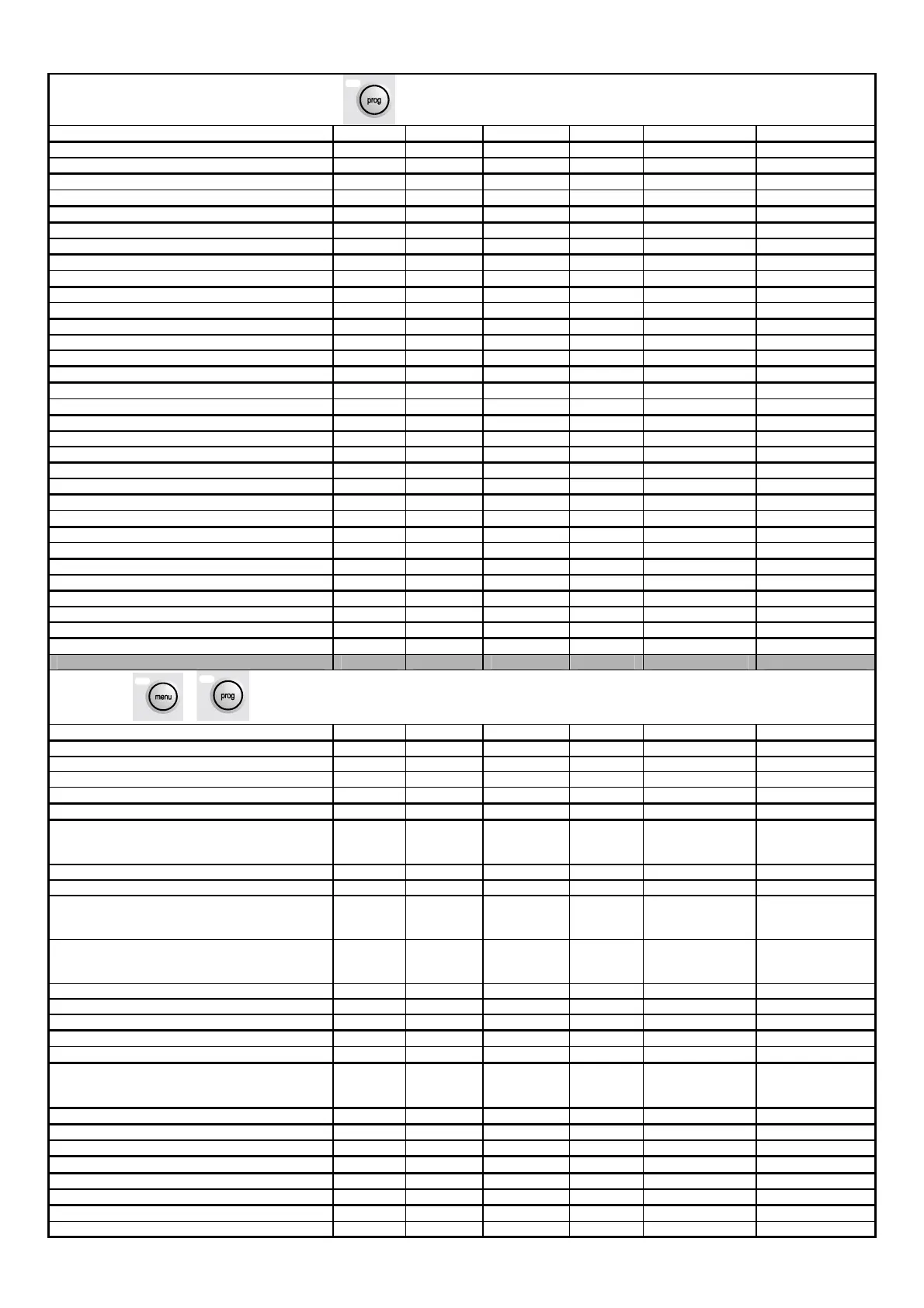
User password inputting P0 M/S 1234 0 to 9999
Minimum limit of summer set-point P1 M 7.0 -99.9 / 99.9 °C
Minimum limit of summer set-point P1 M 17.0 -99.9 / 99.9 °C
Minimum limit of winter set-point P2 M 40.0 -99.9 / 99.9 °C
Minimum limit of winter set-point P2 M 50.0 -99.9 / 99.9 °C
Selection of control probe P3 M Input Input / Output
Control at output - delayed power up P4 M/S 20 0 to 9999 seconds
Control at output - delayed power down P4 M/S 10 0 to 9999 seconds
Control at output - summer forced power down P5 M/S 10.0 -99.9 / 99.9 °C
Control at output - winter forced power down P5 M/S 47.0 -99.9 / 99.9 °C
Control with probe at evaporator input P6 M Prop. Prop./Prop+Int.
Integration time P6 M 0 to 9999 600 seconds
Enable outside set-point P7 M N. N/Y
Outside set-point minimum value P7 M 0.0 -99.9 / 99.9 °C
Outside set-point maximum value P7 M 5.0 -99.9 / 99.9 °C
Control band P8 M 3.0 0 to 99.9 °C
Delayed power up between pump and compressors P9 M 5 0 to 999 seconds
Delayed power down of main pump P9 M 5 0 to 999 seconds
Enable language screen start-up Pa M N. N/Y
Enable remote On/Off Pa M N. N/Y
Enable summer / winter selection from digital input Pa M N. N/Y
Enable On/Off from supervisor Pb M N/Y
Enable summer / winter selection from supervisor Pb M N/Y
Delta freecooling Pc M/S 2.0 0 to 99.9 °C
Freecooling differential Pc M/S 3.0 -99.9 / 99.9 °C
Defrosting starts Pd M 2.0 -99.9 / 99.9 °C/bar
Defrosting ends Pd M 12.0 -99.9 / 99.9 °C/bar
Delayed defrosting start Pe M/S 1800 0 to 32000 seconds
Maximum defrosting time Pe M/S 300 0 to 32000 seconds
Card identification number for supervision network Pf M/S 1 0 to 200
Card communication speed for supervision network Pf M/S 19200 1200 to 19200 bps
Selection of communication serial network Pf M/S Carel Carel / Modbus
New user password inputting Pj M/S 1234 0 to 9999
+
Constructor password inputting Z0 M/S 1234 0 to 9999
Unit configuration C0 M/S 4 0 to 5
Total number of compressors C0 M/S 1 1 to 4
Number of local compressors C0 M/S 1 1 to 2
Number of capacity stages per compressor C0 M/S 3 0 to 3
Enable local power down from flow-switch alarm C1 S S N/Y
Enable probe B1 C2 M/S Y (if pCO2)
N (if pCO1)
N (if pCOC)
N/Y
Enable probe B2 C2 M/S N. N/Y
Enable probe B3 C2 M/S N. N/Y
Enable probe B4 C2 M/S Y (if pCO2)
N (if pCO1)
N (if pCOC)
N/Y
Enable probe B5 C2 M/S Y (if pCO2)
N (if pCO1)
N (if pCOC)
N/Y
Enable probe B6 C2 M/S N. N/Y
Enable probe B7 C2 M/S N. N/Y
Enable probe B8 C2 M/S N. N/Y
Pressure probes minimum limit C3 M/S 00,0 -99.9 to 99.9 bar
Pressure probes maximum limit C3 M/S 30,0 -99.9 to 99.9 bar
Probe type for outside set-point C4 M 4-20 mA 0-20 mA / 4-20
mA
0-1 V / 0-10 V
Number of drivers present C5 M/S 1 1 to 2
Part winding time C6 M/S 1000 5 to 1000 msec
Enable compressor rotation C6 M/S S N/Y
Enable clock card C7 M/S N. N/Y
Enable pump - down C8 M/S N. N/Y
Minimum pump - down time C8 M/S 60 0 to 999 seconds
Delay between capacity controls C9 M 1 0 to 99 seconds
Capacity controls logic C9 M N.C. N.C / N.A.

 Loading...


