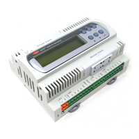
Modular Standard HP Chiller for Carel driver
Carel code +030221236- Rel. 1.0 dated 7 July 2003
16
Compressor minimum ON time Ca M 60 0 to 9999 seconds
Compressor minimum OFF time Ca M 360 0 to 9999 seconds
Minimum time between power ups of different
compressors
Cb M 10 0 to 9999 seconds
Minimum time between power ups of same
compressor
Cb M 450 0 to 9999 seconds
Type of condensation control Cc Pressure No / Pressure
Temperature
Type of condensation management Cc M/S Inverter Inverter / Steps
Type of condensation Cd M/S Single Single / Double
Number of fans per condenser Cd M/S 1 1 to 3
Condensation set-point Ce M/S 14,0 -999.9 to 999.9 bar/ °C
Condensation differential Ce M/S 2,0 -999.9 to 999.9 bar/ °C
Inverter maximum speed Cf M/S 10,0 0.0 to 10.0 V
Inverter maximum speed Cf M/S 0,0 0.0 to 10.0 V
Minimum ON time Cf M/S 0 0 to 999 seconds
Enable prevent Cg M/S S N/Y
Type of control probe Cg M/S Pressure Pressure
/Temperature
Prevent set-point Cg M/S 20,0 -99.9 to 99.9 bar/ °C
Prevent differential Cg M/S 2,0 -99.9 to 99.9 bar/ °C
Set-point for high pressure alarm from transducer Ch M/S 21,0 -99.9 to 99.9 bar
High pressure alarm differential from transducer Ch M/S 2,0 -99.9 to 99.9 bar
Delayed start due to low pressure alarm Ci M/S 40 0 to 999 seconds
Delayed steady state operation due to low pressure
alarm
Ci M/S 0 0 to 999 seconds
Delayed start due to oil differential alarm Cj M/S 120 0 to 999 seconds
Delayed steady state operation due to oil differential
alarm
Cj M/S 10 0 to 999 seconds
Antifreeze alarm set-point Ck M/S 3,0 -99.9 to 99.9 °C
Antifreeze alarm set-point Ck M/S 1,0 -99.9 to 99.9 °C
Type of antifreeze alarm reset Cl M/S Manual Manual /Autom
Delay antifreeze alarm Cl M/S 0 0 to 999 minutes
Antifreeze heater set point Cm M/S 5,0 -99.9 to 99.9 °C
Antifreeze heater differential Cm M/S 1,0 -99.9 to 99.9 °C
Delayed start due to evaporator flow-switch alarm Cn M/S 15 0 to 999 seconds
Delayed steady state operation due to evaporator
flow-switch alarm
Cn M/S 3 0 to 999 seconds
Delayed start due to condenser flow-switch alarm Co M/S 15 0 to 999 seconds
Delayed steady state operation due to condenser
flow-switch alarm
Co M/S 3 0 to 999 seconds
Modulating valve configuration Cp M 0-10 V 0-10 V / On-Off
Cycle reversing valve configuration Cq M/S N.O. N.C / N.A.
Defrosting probe configuration Cr M/S Temperature Temperature
Pressure switch
Type of overall defrosting Cr M/S Simultaneous Simultaneous
Separate
Independent
Type of local defrosting Cr M/S Simultaneous Simultaneous
Separate
Installation of default values Cs M/S N. N/Y
Input new Constructor password Ct M/S 1234 0 to 9999
Input new constructor-driver password Cu M/S 1234 0 to 9999
CAREL EXV DRIVERS
Driver 1 valve type F0 M/S Custom 0-11 (see page 8)
Enable driver 1 battery F0 M/S N. N/Y
Percentage relationship between Refrigerating power
and Driver 1 power
F1 M/S 60 0 to 100 %
Driver 2 valve type F2 M/S Custom 0-11 (see page 8)
Enable driver 2 battery F2 M/S N. N/Y
Percentage relationship between Refrigerating power
and Driver C2 power
F3 M/S 60 0 to 100 %
Driver 1 superheat set-point during chiller operation F4 M/S 6,0 2.0 to 50.0 °C
Driver 1 dead band during chiller operation
F4 M/S 0 0 to 9.9 °C
Driver 1 superheat set-point during heat pump
operation
F5 M/S 6,0 2.0 to 50.0 °C
Driver 1 dead band during heat pump operation
F5 M/S 0 0 to 9.9 °C
Driver 1 superheat set-point during defrost. operation F6 M/S 6,0 2.0 to 50.0 °C
Driver 1 dead band during defrost. operation
F6 M/S 0 0 to 9.9 °C
Driver 2 superheat set-point during chiller operation F7 M/S 6,0 2.0 to 50.0 °C
Driver 2 dead band during chiller operation
F7 M/S 0 0 to 9.9 °C
Driver 2 superheat set-point during heat pump
operation
F8 M/S 6,0 2.0 to 50.0 °C
Driver 2 dead band during heat pump operation
F8 M/S 0 0 to 9.9 °C

 Loading...