118
Fan On Set Point (F. O N ) is Head Setpoint On (H.SP) ex-
cept after a fan stage increase, when Head Setpoint On (H.SP)
is increased by Fan Stage Delta (F. D L T ) for the Fan Delta Ac-
tive Time (F. T M E ). Using the factory default settings results
in the following values: F. O N =115.0 F (46.1 C) or following a
fan stage increase, F. O N =130 F [115.0 + 15.0 F] (54.4 C [46.1
+ 8.3 C]) for 60 seconds following the fan stage increase.
Fan Off Set Point (F. O F F ) is Head Setpoint Off (H.SP.F).
Using the factory default settings results in the following value:
F. O F F =72.0 F (22.2 C).
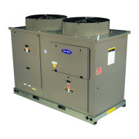
38APD025-060
— The 38APD025-060 units have common
fan control; both circuits share the same condenser fans. When
the highest SCT of both circuits is greater than F. O N , then an
additional stage of fan will be added to the current fan stage.
F. O N will be updated for the required time. A fan stage will
decrease if the SCT for both circuit is less than F. O F F for 2
minutes.
38APS025-065
— For 38APS025-065 units, when the circuit
SCT is greater than F. O N , then an additional stage of fan will
be added to the current fan stage. F. O N will be updated for the
required time. A fan stage will decrease if the circuit’s SCT is
less than F. O F F for 2 minutes
38APD070
— The 38APD070 unit uses an additional fan
stage when the ambient temperature is less than 32 F (0 °C)
and only one circuit is on, Fan Stage 1. This fan stage turns on
the fans in the opposite circuit to draw a lower air volume
across the active circuit coils. (This fan stage is not used if
Motormaster
®
control is used.) When the circuit SCT is
greater than F. O N , then an additional stage of fan will be
added to the current fan stage. F. O N will be updated for the
required time. A fan stage will decrease if the circuit’s SCT is
less than F. O F F for 2 minutes.
38APD080-130
— The 38APD080-130 units have some fans
that are common between both circuits and some that are con-
trolled by each circuit individually. Initial fan stages are circuit-
specific fans and are controlled by the circuit’s SCT. When the
circuit SCT is greater than F. O N , then an additional stage of
fan will be added to the current fan stage. F. O N will be
updated for the required time.
The common fans are controlled by the circuit with the
highest SCT. If the next fan stage is a common fan stage and
one circuit’s SCT is greater than F. O N , the next fan stage will
be energized. F. O N will be updated for the required time.
A fan stage will decrease if the circuit’s SCT is less than
F. O F F for 2 minutes.
Table 44 — Head Pressure Control Settings
Table 45 — 38APD,APS025-030 Fan Staging
*Items in either Service Test
OUTS or Outputs
GEN.O.
†Motormaster controlled motor, if equipped.
SETPOINTS
HEAD
ITEM DISPLAY EXPANSION COMMENTS
H.SP XXX.X °F (°C) Head Setpoint On
Range: 85.0 to 120.0 F (29.4 to 48.9 C)
Default: 115.0 F (46.1 C)
H.SP.F XX.X °F (°C) Head Setpoint Off
Range: 45.0 to 90.0 F (7.2 to 32.2 C)
Default: 72.0 F (22.2 C)
F.ON XXX.X °F (°C) Fan On Set Point Calculated value, cannot be changed
F.OFF XXX.X °F (°C) Fan Off Set Point Calculated value, cannot be changed
F.DLT XX.X 'F ('C) Fan Stage Delta
Range: 0.0 to 50.0 'F (0.0 to 27.8 'C)
Default: 15.0 'F (8.3 'C)
F.TME XXX secs Fan Stage Active Time
Range: 0 to 300 seconds
Default: 60 seconds
UNIT OPERATING CIRCUIT FAN STAGE OUTPUT POINT NAME* CONTACTOR FANS ENERGIZED
38APD025,027,030,
38APS025, 027,030
With or Without Motormaster
Controller
A (38APS)
A or B (38APD)
1FAN1FC1OFM1†
2
FAN1
FAN2
FC1
FC2
OFM1†
OFM2

 Loading...


