The BACview®6 device
BACview® CARRIER CORPORATION ©2021
Installation and User Guide All rights reserved
16
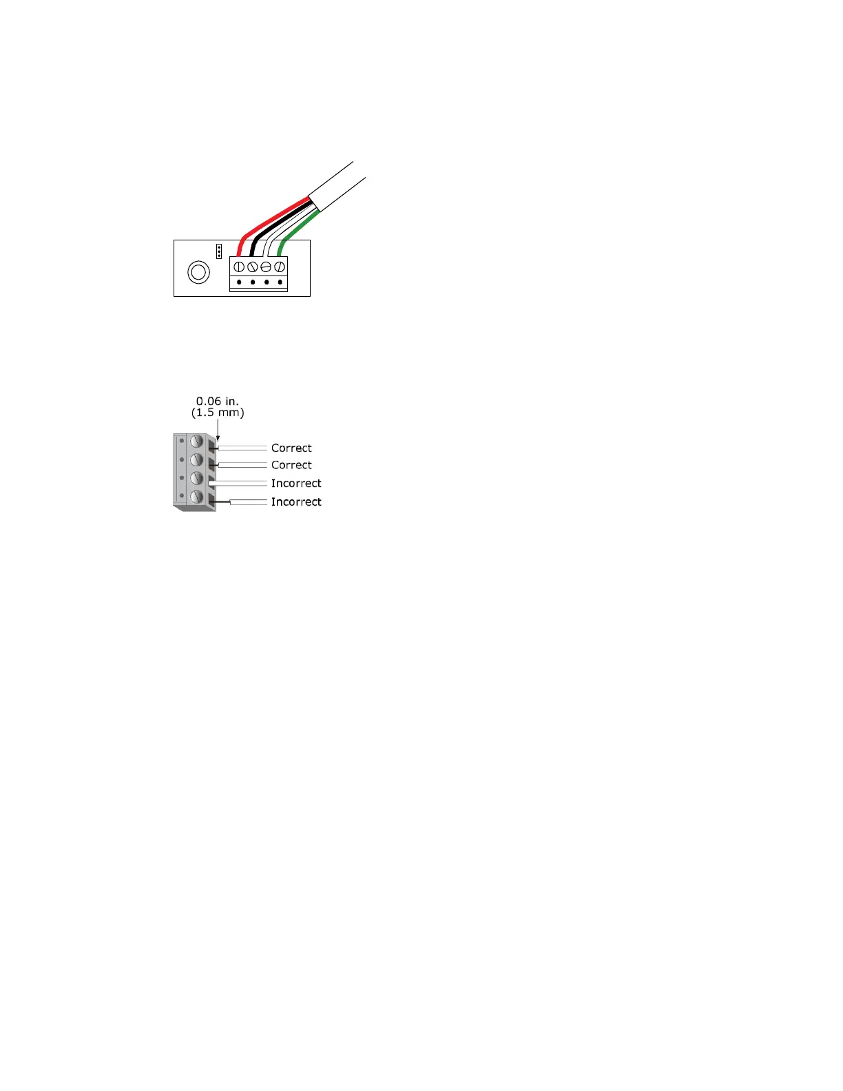
4 Insert the other 4 wires into the BACview®
6
device's screw terminal connector. If wiring 2 cables, insert like-
colored wires into each terminal.
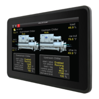
CAUTION Allow no more than .06 inch (1.5 mm) bare communication wire to protrude. If bare communication
wire contacts a metal surface other than the terminal block, the sensor may not communicate correctly.
5 Insert the screw terminal connector into the BACview®
6
device with the screw heads facing out.
NOTE If mounting the BACview®
6
device on a panel door, feed the cable through the door cutout.
6 Connect the other end of the cable to the controller's Rnet port or to an SPT sensor.
NOTES
○ Insert the shield wire with the ground wire into the controller's GND terminal.
○ Use the same polarity throughout the Rnet.
7 Turn on the controller's power.