KC_
SERIES
10
11. Caulk joints in wood frame as required. If wall
thickness is 7-in. or more, add aluminum flashing
over bottom of frame opening to ensure no water
can enter area between inner and outer wall.
12. Remove the chassis from the unit cabinet.
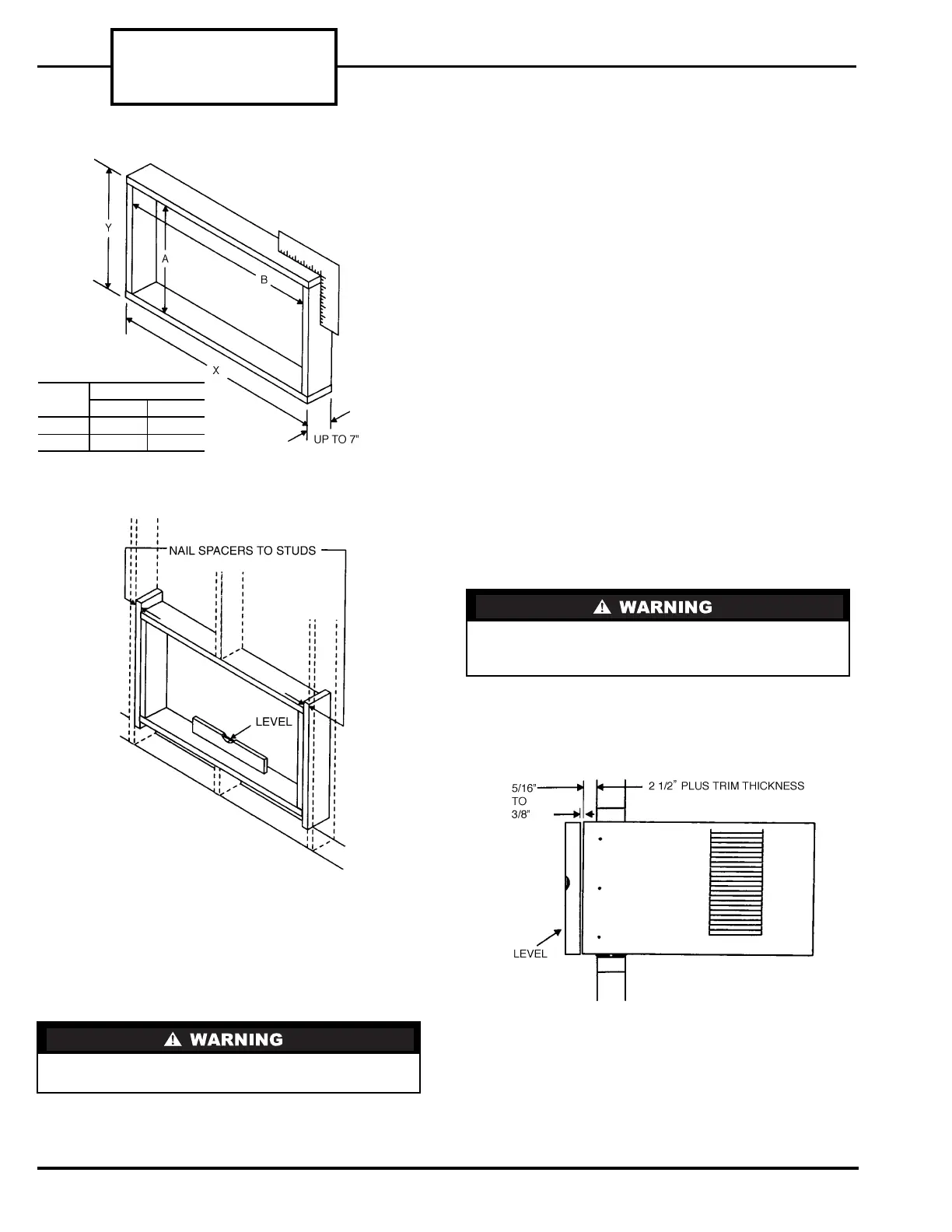
13. Slide the empty cabinet into the wall opening and
into wooden frame. Approximately 2
1
/
2
in. of the
cabinet should be in the room. The rest of the cab-
inet should be positioned through and outside the
wall. See Fig. 23. Maintain proper slope for con-
densate drain operation. Bottom rail should be
resting firmly on bottom board of wooden frame.
14. Secure bottom rail to wood frame with two large
wood screws (1-in. long) using the two holes in the
bottom of the channel. See Fig. 24.
15. There are screw holes in the cabinet (4 each side,
4 top) which are used to secure the cabinet to the
wooden frame. With the cabinet in its final posi-
tion, drill holes in the wooden frame using the
screw holes in the cabinet as a guide. After the
holes have been drilled, secure the cabinet to the
wooden frame using field-supplied screws. See
Fig. 25.
16. Caulk around wood frame and wall opening on
outside wall for a water-tight seal.
17. Optional caulking between the cabinet and the
wooden frame may be done on inside wall. Caulk-
ing provides an air seal around the cabinet. Deco-
rative wood trim may be added to provide a more
pleasing appearance.
18. Lift chassis and carefully slide it into the cabinet.
Be sure that it is firmly seated towards the rear of
the cabinet.
19. Install the front panel.
20. Plug in the unit.
Be careful when handling chassis. Sharp edges on
coil fins can cause personal injury.
Do not push on the controls or the coil when
installing chassis. Damage to unit or personal
injury could result.
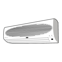
FIGURE 21 — FRAME CONSTRUCTION
UNIT
73KC_
DIMENSIONS (in.)
AB
101P 14.8 20.5
121P 15.7 22.8
FIGURE 22 — FRAME INSTALLATION
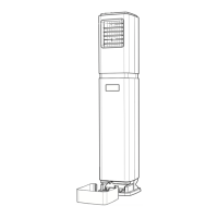
FIGURE 23 — CABINET LOCATION
IN WALL
 Loading...